
Release Notes G.07. 53

Enhancements in Release G.07.xx
Correction to the Management and Configuration Guide
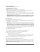
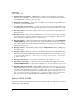
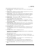
For example, figure 2 illustrates a routing topology with two possible gateways to support a static
route from switch “A” to the 10.31.224.0 network in switch “C”.
VLAN 29: 10.29.224.1
VLAN 30: 10.30.224.3
Switch “A”
VLAN 29: 10.29.224.2
VLAN 30: 10.30.224.1
Switch “B”
VLAN 30: 10.30.224.2
VLAN 31: 10.31.224.1
Switch “C”
Destination Network
In this example, a static route to
the 10.31.224.0 network has been
configured in switch “A”. In this
case, 10.30.224.1 is the configured
gateway.
Figure 2 Example of a Routed Network
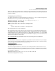
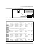
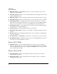
Figure 3 illustrates the show ip route output describing the routes available in the above topology.
Default
Loopback
Network
Default
Loopback
Interface
Default
Null
Route
Configured
Static Route
Destinations
Directly
Connected
to the Switch
Lists the
Data for the
Specified
Route
Figure 3 Examples of the Show IP Route Command
11