
Installation and Reference Guide HP AdvanceStack 100Base-THub-12TX, Hub-12TXM, and Switch Modules 1997-06

HP Hub-12TX/Hub-12TXM Installation and Reference Guide
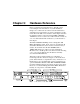
5-6 Hardware Reference
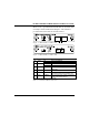
For example, if network utilization reaches 1%, the LED
labeled 1 will light. However, if network utilization rises above
1% (e.g., 30%), the LED labeled 30 and all the other LEDs
before it (i.e., 1, 5, and 15) will light in rapid succession.
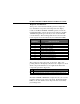
These LEDs monitor the share of valid network frames
transmitted by the stack (or this hub, if isolated) within a
100Mbit/s bandwidth. They provide a quick way to monitor the
current traffic load relative to the capacity available to the
attached collision domain.
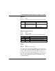
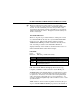
Collision %
Color: Green and yellow
Label (%) Color Function
1, 3, 5 Green Shows percentage of packet collisions occurring
10, 15
+
Yellow out of the total packets received by the hub.
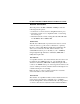
Table 5.9 Collision Indicators
Collisions occur when two or more devices connected to a hub
attempt to transmit data simultaneously on the network. When
a collision occurs, devices pause and then re-transmit after a
pseudo-random wait period. Because wait periods differ among
devices, successive collisions become increasingly improbable.
The
Collision % LEDs assist the network manager in monitoring
the percentage of packet collisions occurring relative to the total
packets received by the stack (or hub, if isolated). Similar to
Utilization % LEDs, the Collision % LEDs have five numbers
representing collision percentage. When collisions reach a level
marked on the LED display, the corresponding LED lights up.
For example, if packet collisions reach 1%, the LED labeled 1
will light up. However, if collisions go beyond 1% (e.g., 15%),
the LED labeled 15
+
and all the other LEDs before it (i.e., 1, 3,
5, and 10) will also light up in rapid succession.