
Switch 7700 Command reference Guide, v2.0
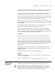
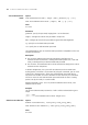
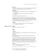
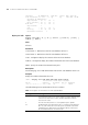
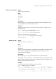
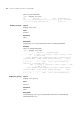
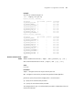
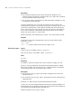


Table Of Contents
- About This Software Version
- Organization of the Manual
- Intended Readership
- Conventions
- Related Manuals
- Logging in Commands
- authentication-mode
- auto-execute command
- command-privilege level
- databits
- display history-command
- display user-interface
- display users
- flow-control
- free user-interface
- header
- history-command max-size
- idle-timeout
- lock
- modem
- modem auto-answer
- modem timer answer
- parity
- quit
- return
- screen-length
- send
- service-type telnet level
- set authentication password
- shell
- speed
- stopbits
- super
- super password
- sysname
- system-view
- telnet
- user-interface
- user privilege level
- Ethernet Port Configuration Commands
- Ethernet Port Link Aggregation Commands
- VLAN Configuration Commands
- GARP Configuration Commands
- GVRP Configuration Commands
- IP Address Configuration Commands
- ARP Configuration Commands
- DHCP Relay Configuration Commands
- IP Performance Configuration Commands
- Routing Table Display Commands
- Static Route Configuration Command
- RIP Configuration Commands
- OSPF Configuration Commands
- abr-summary
- area
- asbr-summary
- authentication-mode
- default cost
- default interval
- default limit
- default tag
- default type
- default-cost
- default-route-advertise
- display ospf abr-asbr
- display ospf asbr-summary
- display ospf brief
- display ospf cumulative
- display ospf error
- display ospf interface
- display ospf lsdb
- display ospf nexthop
- display ospf peer
- display ospf request-queue
- display ospf retrans-queue
- display ospf routing
- display ospf vlink
- filter-policy export
- filter-policy import
- import-route
- network
- nssa
- ospf
- ospf authentication-mode
- ospf cost
- ospf dr-priority
- ospf mtu-enable
- ospf network-type
- ospf timer dead
- ospf timer hello
- ospf timer poll
- ospf timer retransmit
- ospf trans-delay
- peer
- preference
- reset ospf all
- router id
- silent-interface
- spf-schedule-interval
- stub
- vlink-peer
- Integrated IS-IS Configuration Commands
- area-authentication- mode
- default-route-advertise
- display isis interface
- display isis lsdb
- display isis mesh-group
- display isis peer
- display isis route
- display isis spf-log
- domain-authentication- mode
- filter-policy export
- filter-policy import
- ignore-lsp-checksum- error
- import-route
- isis
- isis authentication-mode
- isis circuit-level
- isis cost
- isis dis-priority
- isis enable
- isis mesh-group
- isis timer csnp
- isis timer dead
- isis timer hello
- isis timer lsp
- isis timer retransmit
- is-level
- log-peer-change
- network-entity
- preference
- reset isis all
- reset isis peer
- set-overload
- silent-interface
- spf-delay-interval
- spf-slice-size
- summary
- timer lsp-max-age
- timer lsp-refresh
- timer spf
- BGP Configuration Commands
- aggregate
- bgp
- compare-different-as- med
- confederation id
- confederation nonstandard
- confederation peer-as
- dampening
- debugging bgp
- default local-preference
- default med
- display bgp group
- display bgp network
- display bgp paths
- display bgp peer
- display bgp routing-table
- display bgp routing-table as-path-acl
- display bgp routing-table cidr
- display bgp routing-table community
- display bgp routing-table community-list
- display bgp routing-table dampening
- display bgp routing-table different-origin-as
- display bgp routing-table flap-info
- display bgp routing-table peer
- display bgp routing-table regular-expression
- filter-policy export
- filter-policy import
- group
- import-route
- ip as-path acl
- ip community-list
- network
- peer advertise-community
- peer allow-as-loop
- peer as-number
- peer as-path-acl
- peer connect-interface
- peer default-route-advertise
- peer description
- peer ebgp-max-hop
- peer enable
- peer filter-policy
- peer group
- peer ip-prefix
- peer next-hop-local
- peer public-as-only
- peer reflect-client
- peer route-policy
- peer route-update-interval
- peer timer
- reflect between-clients
- reflect cluster-id
- reset bgp
- reset bgp flap-info
- reset bgp group
- reset dampening
- summary automatic
- timer
- IP Routing Policy Configuration Commands
- apply as-path
- apply community
- apply cost
- apply cost-type
- apply ip next-hop
- apply isis
- apply local-preference
- apply origin
- apply tag
- display ip ip-prefix
- display route-policy
- filter-policy export
- filter-policy import
- if-match { acl | ip-prefix }
- if-match as-path
- if-match community
- if-match cost
- if-match interface
- if-match ip next-hop
- if-match tag
- ip ip-prefix
- route-policy
- Route Capacity Configuration Commands
- GMRP Configuration Commands
- IGMP Snooping Configuration Commands
- Multicast Common Configuration Commands
- PIM Configuration Commands
- ACL Configuration Command List
- QoS Configuration Commands List
- display mirroring-group
- display priority-trust
- display qos cos-local-precedence- map
- display qos-interface queue-scheduler
- display qos-interface all
- display qos-interface traffic-bandwidth
- display qos-interface traffic-limit
- display qos-interface traffic-priority
- display qos-interface traffic-red
- display qos-interface traffic-statistic
- mirroring-group
- priority
- priority trust
- priority-trust
- qos cos-local-precedence- map
- queue-scheduler
- reset traffic-statistic
- traffic-bandwidth
- traffic-limit
- traffic-priority
- traffic-red
- traffic-statistic
- Logon user’s ACL Control Command
- RSTP Configuration Commands
- MSTP Configuration Commands
- active region-configuration
- check region-configuration
- display stp
- display stp region-configuration
- instance
- region-name
- reset stp
- revision-level
- stp
- stp bpdu-protection
- stp bridge-diameter
- stp bridge-priority
- stp edged-port
- stp instance cost
- stp instance port priority
- stp instance root primary
- stp instance root secondary
- stp interface
- stp interface edged-port
- stp interface instance cost
- stp interface instance port priority
- stp interface loop-protection
- stp interface mcheck
- stp interface point-to-point
- stp interface root-protection
- stp interface transit-limit
- stp loop-protection
- stp max-hops
- stp mcheck
- stp mode
- stp point-to-point
- stp region-configuration
- stp root-protection
- stp timer forward-delay
- stp timer hello
- stp timer max-age
- stp transit-limit
- vlan-mapping modulo
- 802.1x Configuration Commands
- AAA Configuration Commands
- RADIUS Protocol Configuration Commands
- data-flow-format
- display local-server statistics
- display radius
- display radius statistics
- display stop-accounting-buffer
- key
- local-server
- primary accounting
- primary authentication
- radius scheme
- reset stop-accounting-buffer
- retry
- retry realtime-accounting
- retry stop-accounting
- secondary accounting
- secondary authentication
- server-type
- state
- stop-accounting-buffer enable
- timer
- timer realtime-accounting
- user-name-format
- VRRP Configuration Commands
- HA Configuration Commands
- File System Management Commands
- Configuration File Management Commands
- FTP Server Configuration Commands
- FTP Client Commands
- TFTP Configuration Commands
- MAC Address Table Management Commands
- Device Management Commands
- Basic System Configuration and Management Commands
- System Status and System Information Display Commands
- System Debug Commands
- Network Connection Test Commands
- Log Commands
- display channel
- display info-center
- info-center console channel
- info-center enable
- info-center logbuffer
- info-center loghost
- info-center monitor channel
- info-center snmp channel
- info-center source
- info-center timestamp
- info-center trapbuffer
- rename channel
- reset logbuffer
- reset trapbuffer
- terminal debugging
- terminal logging
- terminal monitor
- terminal trapping
- SNMP Configuration Commands
- display snmp-agent community
- display snmp-agent
- display snmp-agent group
- display snmp-agent mib-view
- display snmp-agent statistics
- display snmp-agent sys-info contact
- display snmp-agent sys-info location
- display snmp-agent sys-info version
- display snmp-agent usm-user
- snmp-agent local-engineid
- snmp-agent community
- snmp-agent group
- snmp-agent mib-view
- snmp-agent packet max-size
- snmp-agent sys-info
- snmp-agent target-host
- snmp-agent trap enable
- snmp-agent trap life
- snmp-agent trap queue-size
- snmp-agent trap source
- snmp-agent usm-user
- undo snmp-agent
- RMON Configuration Commands
- NTP Configuration Commands
- debugging ntp-service
- display ntp-service sessions
- display ntp-service status
- display ntp-service trace
- ntp-service access
- ntp-service authentication enable
- ntp-service authentication-keyid
- ntp-service broadcast-client
- ntp-service broadcast-server
- ntp-service max-dynamic sessions
- ntp-service multicast-client
- ntp-service multicast-server
- ntp-service refclock-master
- ntp-service reliable authentication-keyid
- ntp-service source-interface
- ntp-service in-interface disable
- ntp-service unicast-peer
- ntp-service unicast-server

164 CHAPTER 5: USING ROUTING PROTOCOL COMMANDS
Interface IP Address Id Link.Sta IP.Sta MTU Type DR
Vlan-interface3 2.1.1.12 001 Up Up 1497 L12 No/No
Secondary IP Address(es):
Csnp-Interval : L1 10 L2 10
Hello-Interval: L1 10 L2 10
Hold Time : L1 30 L2 30
Lsp Interval: 1
Cost : L1 10 L2 10
Priority : L1 64 L2 64
Retransmit Interval: 5
display isis lsdb Syntax
display isis lsdb [ l1 ] [ l2 ] [ level-1 ] [ level-2 ] [ local ] [
verbose ] [ LSPID ]
View
All views
Parameter
l1 and Level-1: Both refer to the link state database of level-1.
l2 and level-2: Both refer to the link state database of level-2.
local: Configure to display the Contents of the Local LSP database.
verbose: Configure to display the verbose information of the link state database.
LSPID: Specify the LSPID of the Network-entity-title.
Description
Use the display isis lsdb command to view the link state database of the IS-IS.
Example
Display the verbose information of an LSP.
<SW7700>display isis lsdb 0050.0500.5005.00-00 verbose
IS-IS Level-1 Link State Database
Lsp ID Sequence Holdtime A-P-OL Checksum
0050.0500.5005.00-00 0x00000328 780 0-0-0 0xf211
The table below gives an explanation of the A-P-O column:
Tab le 7 Description of A-P-O in the IS-IS Link State Database
Heading Meaning
A The Attach bit. Indicates that the router is also a Level 2 router, and it
can reach other areas. Level 1 routers, and Level 2 routers that have lost
connection to other Level 2 routers, used the Attach bit to find the
closest Level 2 router.
P The P bit. This detects if the IS is “area partition repair” capable.
O The Overload bit. This determines if the IS is congested. If the Overload
bit is set, other routers do not use this system as a transit router when
calculating routes. Only packets for destinations directly connected to
the overloaded router are sent to this router.