Switch 7700 Configuration Guide http://www.3com.
3Com Corporation 350 Campus Drive Marlborough, MA 01752-3064 Copyright © 2003, 3Com Corporation. All rights reserved. No part of this documentation may be reproduced in any form or by any means or used to make any derivative work (such as translation, transformation, or adaptation) without written permission from 3Com Corporation.
CONTENTS ABOUT THIS GUIDE Conventions 1 SYSTEM ACCESS Product Overview 3 Function Features 3 Configuring the Switch 7700 4 Setting Terminal Parameters 5 Configuring Through Telnet 8 Configuring Through a Dial-up the Modem 10 Configuring the User Interface 12 Command Line Interface 19 Command Line View 20 Feature and Functions of the Command Line 24 PORT CONFIGURATION Ethernet Port Overview 27 Ethernet Port Configuration 27 Display and Debug Ethernet Port 33 Ethernet Port Troubleshooting 34 Link Aggregat
Configure IP Address 48 Displaying and Debugging an IP Address 49 Troubleshooting an IP Address Configuration 49 ARP Configuration 50 Configure Static ARP 50 DHCP Relay 51 Configuring DHCP Relay 52 Displaying and Debugging DHCP Relay 53 Troubleshooting a DHCP Relay Configuration 55 IP Performance 56 Displaying and Debugging IP Performance 56 Troubleshooting IP Performance 57 ROUTING PROTOCOL OPERATION IP Routing Protocol Overview 59 Route Selection through the Routing Table 60 Routing Management Policy 61
Configure IGMP Snooping 119 Display and debug IGMP Snooping 120 IGMP Snooping Configuration Example 120 TroubleshootinIGMP Snooping 121 Common Multicast Configuration 121 Common Multicast Configuration 122 Display and Debug Common Multicast Configuration IGMP Configuration 123 IGMP Configuration 124 Display and Debug IGMP 126 PIM-DM Configuration 127 PIM-DM Configuration 128 Display and Debug PIM-DM 129 PIM-DM Configuration Example 130 PIM-SM Configuration 131 PIM-SM Operating Principle 131 Preparations bef
Configuring the BPDU Forwarding Mechanism Implementing STP on the Switch 7700 163 Configuring RSTP 164 Displaying and Debugging RSTP 173 163 AAA AND RADIUS OPERATION IEEE 802.1x 177 802.1x System Architecture 177 Configuring 802.1x 179 Displaying and Debugging 802.
Display the State and Information of the System System Debugging 14 Testing Tools for Network Connection 16 Logging Function 16 SNMP 21 SNMP Versions and Supported MIB 21 Configure SNMP 22 Display and Debug SNMP 26 RMON 28 Configure RMON 28 Display and Debug RMON 30 14
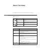
ABOUT THIS GUIDE This guide describes the 3Com® Switch 7700 and how to configure it. Conventions Table 1 and Table 2 list conventions that are used throughout this guide. Table 1 Notice Icons Icon Notice Type Description Information note Information that describes important features or instructions. Caution Information that alerts you to potential loss of data or potential damage to an application, system, or device. Warning Information that alerts you to potential personal injury.
2 ABOUT THIS GUIDE
1 Product Overview SYSTEM ACCESS The 3Com Switch 7700 is a large capacity, modularized wire speed Layer 2/Layer 3 Ethernet switch. It is designed for IP metropolitan area networks (MAN), large-sized enterprise network and campus network users. The Switch 7700 has an integrated chassis structure. The chassis contains a card area, fan area, power supply area, and a power distribution area. In the card area, there are seven slots. Slot 0 is prepared specially for the switch Fabric module.
4 CHAPTER 1: SYSTEM ACCESS Table 1 Function Features Features Support Security features Multi-level user management and password protect 802.
Setting Terminal Parameters Setting Terminal Parameters 5 To set terminal parameters: 1 Start the PC and select Start > Programs > Accessories > Communications > HyperTerminal. 2 The HyperTerminal window displays the Connection Description dialog box, as shown in Figure 2. Figure 2 Set up the New Connection 3 Enter the name of the new connection in the Name field and click OK. The dialog box, shown in Figure 3 displays. 4 Select the serial port to be used from the Connect using dropdown menu.
6 CHAPTER 1: SYSTEM ACCESS 5 Click OK. The Port Settings tab, shown in Figure 4, displays and you can set serial port parameters. Set the following parameters: ■ Baud rate = 9600 ■ Databit = 8 ■ Parity check = none ■ Stopbit = 1 ■ Flow control = none Figure 4 Set Communication Parameters 6 Click OK. The HyperTerminal dialogue box displays, as shown in Figure 5. 7 Select Properties.
Setting Terminal Parameters Figure 5 HyperTerminal Window 8 In the Properties dialog box, select the Settings tab, as shown in Figure 6. 9 Select VT100 in the Emulation dropdown menu. 10 Click OK.
8 CHAPTER 1: SYSTEM ACCESS Configuring Through Telnet After you have correctly configured the IP address of a VLAN interface for an Ethernet switch through the console port (using the ip address command in VLAN interface view), and added the port (that connects to a terminal) to this VLAN (using the port command in VLAN view), you can telnet this Switch 7700 and configure it.
Setting Terminal Parameters 9 5 On the Connect dialog box, enter the IP address of the VLAN connected to the PC port and set the terminal type to VT100, as shown in Figure 9. Figure 9 Connect Ethernet Switch by Telnet The terminal displays User Access Verification and prompts you for the logon password. 6 Enter the password,. The terminal displays the command line prompt (). If the message, Too many users! appears, try to reconnect later.
10 CHAPTER 1: SYSTEM ACCESS Figure 10 Provide Telnet Client Service PC Telnet client Telnet server 1 Authenticate the Telnet user through the console port on the Telnet Server (Ethernet switch) before login. Note: By default, the password is required for authenticating the Telnet user to log in the Ethernet switch. If a user logs in via the Telnet without password, the system displays the following message: Password required, but none set. 2 Enter system view, return to user view by pressing Ctrl+Z.
Setting Terminal Parameters 11 Figure 11 Set Up Remote Configuration Environment Modem serial port line Modem Telephone line PST Modem Console port Remote telephone: 555-5555 3 Dial for a connection to the switch, using the terminal emulator and modem on the remote end. Dial the telephone number of the modem connected to the Ethernet switch. See Figure 12 and Figure 13.
12 CHAPTER 1: SYSTEM ACCESS Figure 13 Dial the Remote PC 4 Enter the preset login password on the remote terminal emulator and wait for the prompt. 5 Use the appropriate commands to configure the Switch 7700 or view its running state. Enter ? to get the immediate help. For details on a specific command, refer to the appropriate chapter in this guide. Note: By default, after login, a modem user can access the commands at Level 0.
Setting Terminal Parameters 13 To number the user interface by relative number, represented by interface + number assigned to each type of user interface: ■ AUX user interface = AUX 0. ■ The first VTY interface = VTY 0, the second one = VTY 1, and so on.
14 CHAPTER 1: SYSTEM ACCESS Table 3 Configure the Attributes of the AUX (Console) Port Operation Command Configure parity mode on the AUX (Console) port. By default, there is no parity bit on the AUX (Console) port parity { even | mark | none | odd | space } Restore the default parity mode undo parity Configure the stop bit of AUX stopbits { 1 | 1.5 | 2 } (Console) port.
Setting Terminal Parameters 15 Configure idle-timeout By default, idle-timeout is enabled and set to 10 minutes on all the user interfaces. The idle-timeout command is described in Table 5. Table 5 Idle Timeout Operation Command Configure idle-timeout idle-timeout minutes [ seconds ] (idle-timeout 0 means disabling idle-timeout.) Restore the default idle-timeout undo idle-timeout Lock user interface This command locks the current user interface and prompts the user to enter a password.
16 CHAPTER 1: SYSTEM ACCESS Configure the Authentication Method The authentication-mode command configures the user login authentication method that denies access to an unauthorized user. Table 9 describes the authentication-mode command. Perform the following configuration in user interface view.
Setting Terminal Parameters 17 Note: By default, the password is required for authenticating the modem and Telnet users when they log in. If the password has not been set, when a user logs in, the following message displays, Password required, but none set. If the authentication-mode none command is used, the modem and Telnet users are not required to enter a password. Set the Command Level after Login The following command is used for setting the command level used after a user logs in.
18 CHAPTER 1: SYSTEM ACCESS Perform the following configuration in system view. Table 13 Set Command Priority Operation Command Set the command priority in a specified view. command-privilege level level view view command Restore the default command level in a specified view. undo command-privilege view view command Configure the Attributes of a Modem You can use the commands described in Table 14 to configure the attributes of a modem when logging in to the switch through the modem.
Command Line Interface 19 Perform the following configuration in user interface view. Table 16 Configure Automatic Command Execution Operation Command Configure to automatically run the command auto-execute command text Configure not to automatically run undo auto-execute command the command Note the following points: ■ After executing the auto-execute command, the user interface can no longer be used to carry out the routine configurations for the local system. Use this command with caution.
20 CHAPTER 1: SYSTEM ACCESS Command Line View ■ Network test commands, such as Tracert and Ping, for rapid troubleshooting of the network. ■ Detailed debugging information to help with network troubleshooting. ■ Ability to log in and manage other Ethernet switches directly, using the telnet command. ■ FTP service for the users to upload and download files. ■ A function similar to Doskey to execute a history command.
Command Line Interface The command line provides the following views: ■ User view ■ System view ■ Ethernet Port view ■ VLAN view ■ VLAN interface view ■ Local-user view ■ User interface view ■ FTP client view ■ Cluster view ■ PIM view ■ RIP view ■ OSPF view ■ OSPF area view ■ Route policy view ■ Basic ACL view ■ Advanced ACL view ■ Interface-based ACL view ■ Layer-2 ACL view ■ RADIUS server group view ■ ISP domain view The relation diagram of the views is shown in Fi
22 CHAPTER 1: SYSTEM ACCESS Figure 14 Relation Diagram of the Views Ethernet port view User interface viiew VLAN view VLAN interface view RIP view OSPF view OSPF area view Route policy view User view Basic ACL view System view Advanced ACL view Interface-based ACL view Layer-2 ACL view FTP client view Local-user view PIM view RADIUS server group view The Table 18 describes the function features of different views and the commands to enter or quit.
Command Line Interface 23 Table 18 Function Feature of Command View Command view Function Prompt VLAN interface view Configure IP interface parameters for a VLAN or a VLAN aggregation [SW7700-Vlaninterface1] Local-user view Configure local user parameters [SW7700-useruser1] User interface view Configure user interface parameters [SW7700-ui0] FTP Client view Configure FTP Client parameters [ftp] Command to enter Command to exit Key in interface vlan-interface 1 in System view quit returns
24 CHAPTER 1: SYSTEM ACCESS Table 18 Function Feature of Command View Feature and Functions of the Command Line Command view Function Prompt Layer-2 ACL view Define the rule of layer-2 ACL [SW7700-acllink-200] RADIUS server group view Configure radius parameters ISP domain view Configure ISP domain parameters Command to enter Command to exit Key in acl number 200 in System view quit returns to System view return returns to user view [SW7700-radius- Key in radius 1] scheme 1 in System view
Command Line Interface 25 -v Verbose output. ICMP packets other than ECHO_RESPONSE that are received are listed STRING<1-20> IP address or hostname of a remote system Ip IP Protocol ■ Enter a command with a ?, separated by a space. If this position is for parameters, all the parameters and their brief descriptions will be listed.
26 CHAPTER 1: SYSTEM ACCESS Table 20 Retrieve History Command Result Operation Key Retrieve the previous history command Up cursor key <> or Retrieves the previous history command, if there is any. Retrieve the next history Down cursor key <> or command Retrieves the next history command, if there is any. Note: Cursor keys can be used to retrieve the history commands in Windows 3.X Terminal and Telnet.
PORT CONFIGURATION 2 This chapter covers the following topics: Ethernet Port Overview ■ Ethernet Port Overview ■ Link Aggregation Configuration A brief description of Switch 7700 I/O modules are listed below: ■ 48-port 10/100Base-T auto-sensing fast Ethernet card ■ 8-port 1000Base-X (Gigabit Interface Converter or GBIC) Gigabit Ethernet card ■ 8-port 10/100/1000Base-T Gigabit Ethernet card ■ 24-port 100Base-FX MMF fast Ethernet card The Ethernet ports of the Switch 7700 have the following fe
28 CHAPTER 2: PORT CONFIGURATION ■ Setting Link Type for Ethernet Port ■ Adding the Ethernet Port to a VLAN ■ Setting the Default VLAN ID for Ethernet Port Entering Ethernet Port View Before configuring the Ethernet port, enter Ethernet port view first. Perform the following configuration in system view. Table 1 Enter Ethernet Port View Operation Command Enter Ethernet port view interface {Gigabit | Ethernet} slot/subslot/port Note: In the Switch 7700, the subslot is always 0.
Ethernet Port Overview 29 Perform the following configuration in Ethernet port view. Table 4 Set Duplex Attribute for Ethernet Port Operation Command Set duplex attribute for Ethernet port. duplex {auto | full | half} Restore the default duplex attribute of Ethernet port. undo duplex Note: 100M electrical Ethernet port can operate in full-duplex, half-duplex or auto-negotiation mode. The Gigabit electrical Ethernet port can operate in full duplex, half duplex or auto-negotiation mode.
30 CHAPTER 2: PORT CONFIGURATION Table 6 Set the Type of the Cable Connected to the Ethernet Port Operation Command Restore the default type of the cable connected to the Ethernet port. undo mdi Note: The settings only take effect on 10/100Base-T and 10/100/1000Base-T ports. The Switch 7700 only supports auto (auto-sensing). If you set some other type, you will see the prompt “Not support this operation!”. The cable type is auto (auto-recognized) by default.
Ethernet Port Overview 31 Setting the Maximum MAC Addresses an Ethernet Port can Learn Use the following command to set an amount limit on MAC addresses learned by the Ethernet port. If the number of MAC address learned by this port exceeds the value set by the user, this port will not learn MAC address. Perform the following configuration in Ethernet port view.
32 CHAPTER 2: PORT CONFIGURATION Adding the Ethernet Port to a VLAN The following commands are used for adding an Ethernet port to a specified VLAN. The access port can only be added to one VLAN, while the hybrid and trunk ports can be added to multiple VLANs. Perform the following configuration in Ethernet port view.
Ethernet Port Overview 33 Table 12 Set the Default VLAN ID for the Ethernet Port Operation Command Restore the default VLAN ID of the trunk port to the default value undo port trunk pvid Note: Display and Debug Ethernet Port ■ The Trunk port and isolate-user-vlan cannot be configured simultaneously, while the hybrid port and isolate-user-vlan can be thus configured.
34 CHAPTER 2: PORT CONFIGURATION Figure 1 Configure the Default VLAN for a Trunk Port Switch A Switch B The following configurations are used for Switch A. Configure Switch B in the similar way. 1 Enter the Ethernet port view of Ethernet1/0/1. [SW7700] interface ethernet1/0/1 2 Set the Ethernet1/0/1 as a trunk port and allows VLAN 2, 6 through 50, and 100 to pass through. [SW7700-Ethernet1/0/1] port link-type trunk [SW7700-Ethernet1/0/1] port trunk permit vlan 2 6 to 50 100 3 Create the VLAN 100.
Link Aggregation Configuration 35 Perform the following configuration in system view. Table 14 Aggregating Ethernet Ports Operation Command Aggregate Ethernet ports link-aggregation port_num1 to port_num2 {both | ingress} Remove a configured link aggregation undo link-aggregation {master_port_num | all} Note: The Ethernet ports to be aggregated should be configured with the same speed and duplex otherwise, they cannot be aggregated. The Switch 7700 does not support ingress aggregation mode.
36 CHAPTER 2: PORT CONFIGURATION Mode: both Ethernet Link Aggregation Troubleshooting When configuring link aggregation, you might see a message that the configuration has failed. To address this situation: ■ Check the input parameter and see whether the starting number of Ethernet port is smaller than the end number. If yes, take the next step. ■ Check whether the Ethernet ports that are in the configured range belong to any other existing link aggregations. If not, take the next step.
3 VLAN Overview VLAN CONFIGURATION A virtual local area network (VLAN) groups the devices of a LAN logically, but not physically, into segments to implement the virtual workgroups. Using VLAN technology, network managers can logically divide the physical LAN into different broadcast domains. Every VLAN contains a group of workstations with the same demands. The workstations of a VLAN do not have to belong to the same physical LAN segment.
38 CHAPTER 3: VLAN CONFIGURATION Add Ethernet Ports to a VLAN You can use the following command to add Ethernet ports to a VLAN. Perform the following configuration in VLAN view.
VLAN Overview 39 Set or Delete VLAN Description Character String You can use the following command to set or delete VLAN description character string. The description character strings, such as workgroup name and department name, are used to distinguish the different VLANs. Perform the following configuration in VLAN view.
40 CHAPTER 3: VLAN CONFIGURATION Perform the following configuration in VLAN interface view. Table 7 Shut Down or Enable a VLAN interface Operation Command Shut down the VLAN interface shutdown Enabling the VLAN interface undo shutdown The operation of shutting down or enabling the VLAN interface has no effect on the status of the Ethernet ports on the local VLAN.
GARP/GVRP Configuration 41 [SW7700-vlan2] port Ethernet 1/0/1 Ethernet 2/0/1 3 Create VLAN 3 and enters its view. [SW7700-vlan2] vlan 3 4 Add Ethernet 1/0/2 and Ethernet 2/0/2 to VLAN3. [SW7700-vlan3] port Ethernet 1/0/2 Ethernet 2/0/2 GARP/GVRP Configuration Generic Attribute Registration Protocol (GARP), offers a mechanism that is used by the members in the same switching network to distribute, propagate, and register information such as VLAN and multicast addresses.
42 CHAPTER 3: VLAN CONFIGURATION Setting the GARP Timer GARP timers include the hold, join, leave, and leaveall timers. The GARP participant sends join message regularly when join timer times out so that other GARP participants can register its attribute values. When the GARP participant wants to remove some attribute values, it sends a leave message outward. The GARP participant receiving the information starts the leave timer.
GARP/GVRP Configuration 43 Table 10 Display and Debug GARP Configuring GVRP Operation Command Display GARP timer display garp timer [ interface interface-list ] Reset GARP statistics information reset garp statistics [ interface interface-list ] Enable GARP event debugging debugging garp event Disable GARP event debugging undo debugging garp event GARP VLAN Registration Protocol (GVRP) is a GARP application.
44 CHAPTER 3: VLAN CONFIGURATION Perform the following configurations in Ethernet port view. Table 12 Enable/Disable Port GVRP Operation Command Enable port GVRP gvrp Disable port GVRP undo gvrp GVRP should be enabled globally before it is enabled on the port. GVRP can only be enabled or disabled on a Trunk port. By default, global GVRP is disabled. Set GVRP Registration Type The GVRP registration types include normal, fixed and forbidden (see IEEE 802.1Q).
GARP/GVRP Configuration 45 Table 14 Display and Debug GVRP Example: GVRP Configuration Example Operation Command Disable GVRP packet or event debugging undo debugging gvrp { packet | event} The network requirement is to dynamically register and update VLAN information among switches. Figure 2 GVRP Configuration Example E1/01 E2/0/1 Switch B Switch A Configure Switch A: 1 Set Ethernet1/0/1 as a Trunk port and allows all the VLANs to pass through.
46 CHAPTER 3: VLAN CONFIGURATION
4 NETWORK PROTOCOL OPERATION This chapter covers the following topics: Configure IP Address ■ Configure IP Address ■ ARP Configuration ■ DHCP Relay ■ IP Performance IP address is a 32-bit address represented by four octets. IP addresses are divided into five classes: A, B, C, D and E. The octets are set according to the first a few bits of the first octet.
48 CHAPTER 4: NETWORK PROTOCOL OPERATION With the rapid development of the Internet, IP addresses are depleting very fast. The traditional IP address allocation method uses up IP addresses with little efficiency. The concept of mask and subnet was proposed to make full use of the available IP addresses. A mask is a 32-bit number corresponding to an IP address. The number consists of 1s and 0s. Principally, these 1s and 0s can be combined randomly.
Configure IP Address 49 Generally, it is sufficient to configure one IP address for an interface. However, you can also configure more than one IP addresses for an interface, so that it can be connected to several subnets. Among these IP addresses, one is the primary IP address and all others are secondary. By default, the IP address of a VLAN interface is null.
50 CHAPTER 4: NETWORK PROTOCOL OPERATION but not receive the ARP packets, there are probably errors on the Ethernet physical layer. ARP Configuration An IP address cannot be directly used for communication between network devices because devices can only identify MAC addresses. An IP address is only the address of a host in the network layer. To send data packets through the network layer to the destination host, the physical address of the host is required.
DHCP Relay 51 Manually Add/Delete Static ARP Mapping Entries Perform the following configuration in System view. Table 4 Manually Add/Delete Static ARP Mapping Entries Operation Command Manually add a static ARP mapping arp static ip-address mac-address VLANID { entry interface_type interface_num | interface_name } Manually delete a static ARP mapping entry undo arp static ip-address Note: Static ARP mapping entries will not time out, however dynamic ARP mapping entries time out after 20 minutes.
52 CHAPTER 4: NETWORK PROTOCOL OPERATION DHCP client Intranet Switch Ethernet DHCP clients Ethernet Figure 2 DHCP Relay Schematic Diagram DHCP server When the DHCP Client performs initialization, it broadcasts the request packet on the local network segment. If there is a DHCP server on the local network segment (e.g. the Ethernet on the right side of the figure), then the DHCP can be configured directly without the relay.
DHCP Relay 53 Configure Corresponding DHCP Server Group of the VLAN Interface Perform the following configuration in VLAN interface view.
54 CHAPTER 4: NETWORK PROTOCOL OPERATION Table 10 Displaying and Debugging DHCP Relay Example: Configuring DHCP Relay Operation Command Enable the DHCP relay debugging debugging dhcp-relay Disable the DHCP relay debugging undo debugging dhcp-relay Display the address information of all the legal clients of the DHCP Server group. display dhcp-security [ ip_address ] Configure the VLAN interface corresponding to the user and the related DHCP server so as to use DHCP relay.
DHCP Relay 55 end in different VLANs. The corresponding interface VLAN of the DHCP Server Group 1 is configured as 4000, and that of the group 2 is configured as 3001. [3Com] vlan 4000 [3Com-vlan4000] port Ethernet 1/0/4 [3Com] interface vlan 4000 [3Com-VLAN-Interface4000] ip address 1.99.255.1 255.255.0.0 [3Com] vlan 3001 [3Com-vlan3001] port Ethernet 1/0/5 [3Com] interface vlan 3001 [3Com-VLAN-Interface3001] ip address 1.88.255.1 255.255.0.0 8 Show the configuration of DHCP server groups in User view.
56 CHAPTER 4: NETWORK PROTOCOL OPERATION IP Performance TCP attributes to be configured include: ■ synwait timer: When sending the syn packets, TCP starts the synwait timer. If response packets are not received before synwait timeout, the TCP connection will be terminated. The timeout of synwait timer ranges 2 to 600 seconds and it is 75 seconds by default. ■ finwait timer: When the TCP connection state turns from FIN_WAIT_1 to FIN_WAIT_2, finwait timer will be started.
IP Performance Troubleshooting IP Performance 57 If the IP layer protocol works normally but TCP and UDP do work normally, you can enable the corresponding debugging information output to view the debugging information. ■ Use the terminal debugging command to output the debugging information to the console. ■ Use the debugging udp command to enable the UDP debugging to trace the UDP packet. When the router sends or receives UDP packets, the content format of the packet can be displayed in real time.
58 CHAPTER 4: NETWORK PROTOCOL OPERATION
5 ROUTING PROTOCOL OPERATION This chapter covers the following topics: IP Routing Protocol Overview ■ IP Routing Protocol Overview ■ Static Routes ■ RIP ■ OSPF ■ IP Routing Policy Routers select an appropriate path through a network for an IP packet according to the destination address of the packet. Each router on the path receives the packet and forwards it to the next router. The last router in the path submits the packet to the destination host.
60 CHAPTER 5: ROUTING PROTOCOL OPERATION Figure 1 About Hops A R R Route Segment R R R C B Networks can have different sizes so the segment lengths connected between two different pairs of routers are also different. If a router in a network is regarded as a node and a route segment in the Internet is regarded as a link, message routing in the Internet works in a similar way as the message routing in a conventional network.
IP Routing Protocol Overview ■ 61 The priority added to the IP routing table for a route — Indicates the type of route that is selected. There may be multiple routes with different next hops to the same destination. These routes can be discovered by different routing protocols, or they can be the static routes that are configured manually. The route with the highest priority (the smallest numerical value) is selected as the current optimal route.
62 CHAPTER 5: ROUTING PROTOCOL OPERATION Routing protocols (as well as the static configuration) can generate different routes to the same destination, but not all these routes are optimal. In fact, at a certain moment, only one routing protocol can determine a current route to a single destination.
Static Routes 63 The following routes are static routes: ■ Reachable route — The normal route in which the IP packet is sent to the next hop by the route marked by the destination. It is a common type of static route. ■ Unreachable route — When a static route to a destination has the reject attribute, all the IP packets to this destination are discarded, and the originating host is informed that the destination is unreachable.
64 CHAPTER 5: ROUTING PROTOCOL OPERATION The IP address and mask use a decimal format. Because the 1s in the 32-bit mask must be consecutive, the dotted decimal mask can also be replaced by the mask-length which refers to the digits of the consecutive 1s in the mask.
Static Routes Table 4 Display and Debug the Routing Table Operation Command view the route filtered through display ip routing-table acl { acl-number | acl-name } [ specified basic access control verbose ] list (ACL) view the route information display ip routing-table ip-prefix ip-prefix-number [ that through specified ip prefix verbose ] list Example: Typical Static Route Configuration View the routing information found by the specified protocol display ip routing-table protocol protocol [ inactive |
66 CHAPTER 5: ROUTING PROTOCOL OPERATION 4 Configure the default gateway of the Host A to be 1.1.1.2 5 Configure the default gateway of the Host B to be 1.1.5.2 6 Configure the default gateway of the Host C to be 1.1.4.1 Using this procedure, all the hosts or switches in Figure 3 can be interconnected in pairs.
RIP ■ 67 Route tag — The indication whether the route is generated by an interior routing protocol or by an exterior routing protocol. The whole process of RIP startup and operation can be described as follows: 1 If RIP is enabled on a router for the first time, the router broadcasts a request packet to adjacent routers.
68 CHAPTER 5: ROUTING PROTOCOL OPERATION Enable RIP and Enter the RIP View Perform the following configurations in system view. Table 5 Enable RIP and Enter the RIP View Operation Command Enable RIP and enter the RIP view rip Disable RIP undo rip By default, RIP is not enabled. Enable the RIP Interface For flexible control of RIP operation, you can specify the interface and configure the network where it is located to the RIP network, so that these interfaces can send and receive RIP packets.
RIP 69 Usually, this command is not recommended because the opposite side does not need to receive two of the same messages at a time. It should be noted that the peer command should also be restricted by rip work, rip output, rip input and network commands. Specify the RIP Version RIP has two versions, RIP-1 and RIP-2. You can specify the version of the RIP packet processed by the interface. RIP-1 broadcasts the packets. RIP-2 can transmit packets by both broadcast and multicast.
70 CHAPTER 5: ROUTING PROTOCOL OPERATION Perform the following configuration in VLAN interface view.
RIP 71 Perform the following configurations in RIP view. Table 12 Route Aggregation Operation Command Activate the automatic aggregation function of RIP-2 summary Disable the automatic undo summary aggregation function of RIP-2 RIP-2 uses the route aggregation function by default. Set RIP-2 Packet Authentication RIP-1 does not support packet authentication. However, you can configure packet authentication on RIP-2 interfaces.
72 CHAPTER 5: ROUTING PROTOCOL OPERATION Perform the following configuration in VLAN interface view. Table 14 Configure Split Horizon Operation Command Enable split horizon rip split-horizon Disable split horizon undo rip split-horizon By default, split horizon of the interface is enabled. Configure RIP to Import Routes of Other Protocols RIP allows users to import the route information of other protocols into the routing table. RIP can import direct, static, OSPF, BGP, and other routes.
RIP 73 Perform the following configurations in RIP view. Table 17 Set the RIP Preference Operation Command Set the RIP Preference preference value Restore the default value of RIP preference undo preference By default, the preference of RIP is 100. Set Additional Routing Metric The additional routing metric is the input or output routing metric added to an RIP route.
74 CHAPTER 5: ROUTING PROTOCOL OPERATION Table 19 Configure RIP to Filter Routes Operation Command Cancel filtering the received routing information distributed by the specified address undo filter-policy gateway ip-prefix-name import Configure filtering the received global routing information filter-policy {acl-number | ip-prefix ip-prefix-name } import Cancel filtering the received global routing information undo filter-policy { acl-number | ip-prefix ip-prefix-name } import Configure RIP to Fil
OSPF 75 Figure 4 RIP Configuration Network address: 155.10.1.0/24 Interface address: 155.10.1.1/24 Switch A Interface address: 110.11.2.1/24 Ethernet Network address: 110.11.2.2/24 Switch B Switch C Interface address: Interface address: 117.102.0.1/16 196.38.165.1/24 Network address: 196.38.165.0/24 Network address: 117.102.0.0/16 Note: The following configuration only shows the operations related to RIP.
76 CHAPTER 5: ROUTING PROTOCOL OPERATION Calculating OSPF Routes ■ Scope — Supports networks in various sizes and can support several hundred routers ■ Fast convergence — Transmits the update packets instantly after the network topology changes so the change is synchronized in the AS ■ Loop-free — Calculates routes with the shortest path tree algorithm according to the collected link states so no loop routes are generated from the algorithm itself ■ Area partition — Allows the network of AS to be
OSPF 77 When two routers synchronize their databases, they use the DD packets to describe their own Link State Databases (LSDs), including the digest of each LSA. The digest refers to the HEAD of an LSA, which can be used to uniquely identify the LSA. Synchronizing databases with DD packets reduces the traffic size transmitted between the routers, since the HEAD of an LSA only occupies a small portion of the overall LSA traffic. With the HEAD, the peer router can judge whether it has already had the LSA.
78 CHAPTER 5: ROUTING PROTOCOL OPERATION topology becomes more likely to change. Hence, the network is always in “turbulence”, and a large number of OSFP packets are generated and transmitted in the network. This shrinks network bandwidth. In addition, each change causes all the routers on the network to recalculate the routes. OSPF solves the this problem by dividing an AS into different areas. Areas logically group the routers, which form the borders of each area.
OSPF ■ Configure NSSA of OSPF ■ Configure the Route Summarization of OSPF Area ■ Configure OSPF Virtual Link ■ Configure Route Summarization Imported into OSPF ■ Configure the OSPF Area to Support Packet Authentication ■ Configure OSPF Packet Authentication ■ Configure OSPF to Import the Routes of Other Protocols ■ Configure Parameters for OSPF to Import External Routes ■ Configure OSPF to Import the Default Route ■ Set OSPF Route Preference ■ Configure OSPF Route Filtering ■ Configu
80 CHAPTER 5: ROUTING PROTOCOL OPERATION Perform the following configuration in OSPF Area view. Table 23 Specify Interface Operation Command Specify an interface to run OSPF network ip-address ip-mask Disable OSPF on the interface undo network ip-address ip-mask You must specify the segment to which the OSPF will be applied after enabling the OSPF tasks. Configure Router ID A router ID is a 32-bit unsigned integer that uniquely identifies a router within an AS.
OSPF 81 the sending polling hello packets before the adjacency of the neighboring routers is formed. ■ Configure the interface type to nonbroadcast on a broadcast network without multi-access capability. ■ Configure the interface type to P2MP if not all the routers are directly accessible on an NBMA network. ■ Change the interface type to P2P if the router has only one peer on the NBMA network.
82 CHAPTER 5: ROUTING PROTOCOL OPERATION Set the Interface Priority for DR Election The priority of the router interface determines the qualification of the interface for DR election, a router of higher priority is considered first if there is a collision in the election. DR is not designated manually, instead, it is elected by all the routers on the segment. Routers with priorities > 0 in the network are eligible candidates.
OSPF 83 broadcasting the Hello packets, you must manually specify an IP address for the adjacent router for the interface, and whether the adjacent router is eligible for election. This can be done by configuring the peer ip-address command. If dr-priority-number is not specified, the adjacent router will be regarded as ineligible. Perform the following configuration in OSPF view. Table 28 Configure the Peer Operation Command Configure a peer for the NBMA interface.
84 CHAPTER 5: ROUTING PROTOCOL OPERATION Table 30 Set a Dead Timer for the Neighboring Routers Operation Command Restore the default dead interval of undo ospf timer dead the neighboring routers By default, the dead interval for the neighboring routers of P2P or broadcast interfaces is 40 seconds and for the neighboring routers of P2MP or NBMA interfaces is 120 seconds. Note that both hello and dead timers restore the default values if you modify the network type.
OSPF 85 Note that a LSA retransmission interval that is too small will cause unnecessary retransmission. Set a Shortest Path First (SPF) Calculation Interval for OSPF Whenever the OSPF LSDB changes, the shortest path requires recalculation. Calculating the shortest path after a change consumes enormous resources and affects the operating efficiency of the router. Adjusting the SPF calculation interval, however, can restrain the resource consumption caused by frequent network changes.
86 CHAPTER 5: ROUTING PROTOCOL OPERATION Table 34 Configure an OSPF STUB Area Operation Command Remove the cost of the default route to the STUB area undo default-cost By default, the STUB area is not configured, and the cost of the default route to a STUB area is 1. Configure NSSA of OSPF NSSA and NSSA LSA (also called Type-7 LSA) are transformations of the STUB area and are highly similar to a STUB area.
OSPF 87 Table 35 Configure NSSA of OSPF Operation Command Restore the default cost value of the route to the NSSA area undo default-cost All routers connected to the NSSA must use the nssa command to configure the area with the NSSA attribute. The default-route-advertise parameter is used to generate the default type-7 LSAs. The default type-7 LSA route is generated on the ABR, even though the default route 0.0.0.0 is not in the routing table.
88 CHAPTER 5: ROUTING PROTOCOL OPERATION Perform the following configuration in OSPF Area view. Table 36 Configure the Route Summarization of an OSPF Area Operation Command Configure the Route Summarization of OSPF Area abr-summary ip-address mask [ advertise | not-advertise ] Cancel route summarization of OSPF Area undo abr-summary ip-address mask By default, the inter-area routes are not summarized.
OSPF 89 The area-id and router-id variables have no default value. By default, the hello timer is 10 seconds, retransmit is 5 seconds, trans-delay is 1 second, and the dead timer is 40 seconds. Configure Route Summarization Imported into OSPF The OSPF implementation in the Switch 7700 supports route summarization of imported routes. Perform the following configurations in OSPF view.
90 CHAPTER 5: ROUTING PROTOCOL OPERATION Perform the following configuration in VLAN interface view.
OSPF 91 Perform the following configuration in OSPF view. Table 41 Configure OSPF to Import the Routes of Other Protocols Operation Command Configure OSPF to impor routes of other protocols import-route protocol [ cost value ] [ type value ] [ tag value ] [ route-policy route-policy-name ] Cancel importing routing undo import-route protocol information of other protocols By default, OSPF does not import the routing information of other protocols.
92 CHAPTER 5: ROUTING PROTOCOL OPERATION Configure OSPF to Import the Default Route The import-route command cannot be used to import the default route. Using the default-route-advertise command, you can import the default route into the routing table. Perform the following configuration in OSPF view.
OSPF 93 By default, OSPF does not filter the imported and distributed routing information. For detailed description, see “IP Routing Policy”. Configure Filling the MTU Field When an Interface Transmits DD Packets OSPF-running routers use the DD (Database Description) packets to describe their own LSDBs when synchronizing the databases. By default, the MTU field in DD packets is 0. You can manually specify an interface to fill in the MTU field in a DD packet when it transmits the packet.
94 CHAPTER 5: ROUTING PROTOCOL OPERATION Perform the following configuration in user view. Table 48 Reset the OSPF Process Operation Command Reset the OSPF process reset ospf all Resetting the OSPF process can immediately clear the invalid LSAs, make the modified Router ID effective or re-elect the DR and BDR. Display and Debug OSPF After configurating OSPF, execute the display command in all views to display the running of the OSPF configuration, and to verify the effect of the configuration.
OSPF 95 Figure 6 Configuring DR Election Based on OSPF Priority Switch A 1.1.1.1 Switch D 4.4.4.4 DR 196.1.1.1/24 196.1.1.4/24 196.1.1.2/24 196.1.1.3/24 BDR 2.2.2.2 Switch B 3.3.3.3 Switch C The commands listed in the following examples enable Switch A and Switch C to be DR and BDR respectively. The priority of Switch A is 100, which is the highest on the network, so it is elected as the DR. Switch C has the second highest priority, so it is elected as the BDR.
96 CHAPTER 5: ROUTING PROTOCOL OPERATION On Switch A, execute the display ospf peer command to display the OSPF neighbors. Note that Switch A has three neighbors. The state of each neighbor is full, which means that adjacency is set up between Switch A and each neighbor. Switch A and Switch C should set up adjacencies with all the routers on the network so that they can serve as the DR and BDR on the network. respectively. Switch A is DR, while Switch C is BDR on the network.
OSPF 97 [Switch A] ospf [Switch A-ospf] area 0 [Switch A-ospf-area-0.0.0.0] network 196.1.1.0 0.0.0.255 2 Configure Switch B: [Switch [Switch [Switch [Switch [Switch [Switch [Switch [Switch [Switch [Switch [Switch [Switch B] interface vlan-interface 7 B-Vlan-interface7] ip address 196.1.1.2 255.255.255.0 B] interface vlan-interface 8 B-Vlan-interface8] ip address 197.1.1.2 255.255.255.0 B] router id 2.2.2.2 B] ospf B-ospf] area 0 B-ospf-area-0.0.0.0] network 196.1.1.0 0.0.0.255 B-ospf-area-0.0.0.
98 CHAPTER 5: ROUTING PROTOCOL OPERATION ■ ■ ■ ■ ■ ■ ■ ■ If the physical link and the lower layer protocol are normal, check the OSPF parameters configured on the interface. The parameters should be the same parameters configured on the router adjacent to the interface. The same area ID should be used, and the networks and the masks should also be consistent. (The P2P or virtually linked segment can have different segments and masks.
IP Routing Policy 99 to enrich its routing knowledge. While importing the routing information, it must import only the information that meets its conditions. To implement the routing policy, you must define a set of rules by specifying the characteristics of the routing information to be filtered. You can set the rules based on such attributes as destination address and source address of the information.
100 CHAPTER 5: ROUTING PROTOCOL OPERATION gateway options and require it to receive only the routing information distributed by certain routers. An ip-prefix is identified by the ip-prefix name. Each ip-prefix can include multiple list items, and each list item can independently specify the match range of the network prefix forms and is identified with a index-number. The index-number designates the matching check sequence in the ip-prefix.
IP Routing Policy 101 The deny argument specifies that the apply clauses are not executed. If a route satisfies all the if-match clauses of the node, the node denies the route and the route does not take the test of the next node. If a route does not satisfy all the if-match clauses of the node, however, the route takes the test of the next node. The router tests the route against the nodes in the route policy in sequence, once a node is matched, the route policy filtering is passed.
102 CHAPTER 5: ROUTING PROTOCOL OPERATION Table 51 Define If-match Conditions Operation Command Match the tag domain of the OSPF routing information if-match tag value Cancel the tag domain of the matched OSPF routing information undo if-match tag By default, no matching is performed. Note that: ■ The if-match clauses for a node in the route policy require that the route satisfy all the clauses to match the node before the actions specified by the apply clauses can be executed.
IP Routing Policy 103 Table 52 Define Apply Clauses Operation Command Cancel the route origin of the BGP routing information undo apply origin Set the tag domain of the OSPF routing information apply tag value Cancel the tag domain of the OSPF undo apply tag routing information By default, no apply clauses are defined.
104 CHAPTER 5: ROUTING PROTOCOL OPERATION Perform the following configurations in system view. Table 54 Define Prefix-list Operation Command Define a prefix list ip ip-prefix ip-prefix-name [ index index-number ] { permit | deny } network len [ greater-equal greater-equal ] [ less-equal less-equal ] Remove a prefix list undo ip ip-prefix ip-prefix-name [ index index-number | permit | deny ] During the matching, the router checks list items identified by the index-number in the ascending order.
IP Routing Policy 105 Perform the following configuration in routing protocol view.
106 CHAPTER 5: ROUTING PROTOCOL OPERATION Figure 9 Filtering Received Routing Information static 20.0.0.1/8 30.0.0.1/8 40.0.0.1/8 1.1.1.1 2.2.2.2 area 0 Switch A Switch B Configure Switch A: 1 Configure the IP address of VLAN interface. [Switch [Switch [Switch [Switch A] interface vlan-interface 100 A-Vlan-interface100] ip address 10.0.0.1 255.0.0.0 A] interface vlan-interface 200 A-Vlan-interface200] ip address 12.0.0.1 255.0.0.0 2 Configure three static routes. [Switch A] ip route-static 20.0.0.
IP Routing Policy 107 ■ The if-match mode of at least one node of the Route policy should be the permit mode. When a Route-policy is used for the routing information filtering, if a piece of routing information does not pass the filtering of any node, then it means that the route information does not pass the filtering of the Route-policy. When all the nodes of the Route-policy are in the deny mode, then all the routing information cannot pass the filtering of the Route-policy.
108 CHAPTER 5: ROUTING PROTOCOL OPERATION
6 MULTICAST PROTOCOL This chapter includes information on the following: IP Multicast Overview ■ IP Multicast Overview ■ GMRP ■ IGMP Snooping ■ Common Multicast Configuration ■ IGMP Configuration ■ PIM-DM Configuration ■ PIM-SM Configuration Many transmission methods can be used when the destination (including data, voice and video) is the secondary use of the network. You should establish an independent data transmission path for each user if the multicast method is used.
110 CHAPTER 6: MULTICAST PROTOCOL Figure 1 Comparison Between the Unicast and Multicast Transmission Receiver Unicast Receiver Server Receiver Receiver Multicast Receiver Server Receiver Note: A multicast source does not necessarily belong to a multicast group. It only sends data to the multicast group and it is not necessarily a receiver. Multiple sources can send packets to a multicast group simultaneously. A router that does not support multicast may exist on the network.
IP Multicast Overview 111 Ranges and meanings of Class D addresses are shown in Table 1. Table 1 Ranges and Meanings of Class D Addresses Class D address range Meaning 224.0.0.0∼224.0.0.255 Reserved multicast addresses (addresses of permanent groups). Address 224.0.0.0 is reserved. The other addresses can be used by routing protocols. 224.0.1.0∼238.255.255.255 Multicast addresses available for users (addresses of temporary groups). They are valid in the entire network. 239.0.0.0∼239.255.255.
112 CHAPTER 6: MULTICAST PROTOCOL Figure 2 Mapping Between the Multicast IP Address and the Ethernet MAC Address 32-bit IP address 5 bits Lower 23 bits directly mapped not mapped 48-bit MAC address Only 23 bits of the last 28 bits in the IP multicast address are mapped to the MAC address. Therefore the 32 IP multicast addresses are mapped to the same MAC address. IP Multicast Protocols Multicast uses the multicast group management protocol and multicast routing protocol.
IP Multicast Overview 113 resources related (such as bandwidth and CPU of routers) are consumed. In order to decrease the consumption of these precious network resources, branches that do not have members send Prune messages toward the source to reduce the unwanted/unnecessary traffic. To enable the receivers to receive multicast data streams, the pruned branches can be restored periodically to a forwarding state.
114 CHAPTER 6: MULTICAST PROTOCOL Application of Multicast IP multicast technology effectively solves the problem of packet forwarding from single-point to multi-point. It implements high-efficient data transmission from single-point to multi-point in IP networks and can save a large amount of network bandwidth and reduce network loads.
GMRP 115 By default, GMRP is disabled. Enabling/Disabling GMRP on the Port Perform the following configuration in Ethernet port view. Table 4 Enabling/Disabling GMRP on the Port Operation Command Enable GMRP on the port gmrp Disable GMRP on the port undo gmrp GMRP should be enabled globally before being enabled on a port. By default, GMRP is disabled on the port.
116 CHAPTER 6: MULTICAST PROTOCOL [SW7700-Ethernet1/0/1] gmrp IGMP Snooping IGMP Snooping (Internet Group Management Protocol Snooping) is a multicast control mechanism running on layer 2. It is used for multicast group management and control. IGMP Snooping runs on the link layer. When receiving the IGMP messages, the Layer 2 Switch 7700 uses IGMP Snooping to analyze the information. If the switch hears IGMP host report message from an IGMP host, it adds the host to the corresponding multicast table.
IGMP Snooping 117 Figure 5 Multicast Packet Transmission with IGMP Snooping Video stream Internet/Intranet Multicast router Video stream VOD server Layer 2 Ethernet switch Video stream Video stream Multicast group member Nonmulticast group member Video stream Nonmulticast group member Implement IGMP Snooping This section introduces related switch concepts of IGMP Snooping: ■ Router Port: The port directly connected to the multicast router.
118 CHAPTER 6: MULTICAST PROTOCOL Figure 6 Implementing IGMP Snooping Internet A router running IGMP IGMP packets An Ethernet switch running IGMP snooping IGMP packets 1 IGMP general query message: Transmitted by the multicast router to query which multicast group contains member. When a router port receives an IGMP general query message, the Switch 7700 will reset the aging timer of the port.
IGMP Snooping 119 any member, the switch will notify the multicast router to remove it from the multicast tree. Configure IGMP Snooping The main IGMP Snooping configuration includes: ■ Enabling/disabling IGMP Snooping ■ Configuring the aging time of router port ■ Configuring maximum response time ■ Configuring the aging time of multicast group member port Of the above configuration tasks, enabling IGMP Snooping is required, while others are optional.
120 CHAPTER 6: MULTICAST PROTOCOL Perform the following configuration in system view. Table 8 Configuring the Maximum Response Time Operation Command Configure the maximum response time igmp-snooping max-response-time seconds Restore the default setting undo IGMP-snooping max-response-time By default, the maximum response time is 10 seconds. Configure Aging Time of Multicast Group Member This task sets the aging time of the multicast group member port.
Common Multicast Configuration 121 Figure 7 IGMP Snooping Configuration Network Internet Router Multicast Switch 1 Display the status of GMRP. display gmrp status 2 Display the current status of IGMP Snooping when GMRP is disabled. display igmp-snooping configuration 3 Enable IGMP Snooping if it is disabled.
122 CHAPTER 6: MULTICAST PROTOCOL Common Multicast Configuration Common multicast configuration includes: ■ Enabling multicast Enabling Multicast Enable multicast first before enabling the multicast routing protocol. Enabling multicast will automatically enable IGMP operation on all interfaces. Perform the following configuration in system view.
IGMP Configuration IGMP Configuration 123 IGMP (Internet Group Management Protocol) is a protocol in the TCP/IP suite responsible for management of IP multicast members. It is used to establish and maintain multicast membership among IP hosts and their connected neighboring routers. IGMP excludes transmitting and maintenance information among multicast routers, which are completed by multicast routing protocols. All hosts participating in multicast must implement IGMP.
124 CHAPTER 6: MULTICAST PROTOCOL multicast group. This prevents the hosts of members of other multicast groups from sending response messages. ■ Max response time The Max Response Time is added in IGMP Version 2. It is used to dynamically adjust the allowed maximum time for a host to response to the membership query message. IGMP Configuration Once multicast is enabled, IGMP will automatically run on each interface. Generally, IGMP does not need to be configured.
IGMP Configuration 125 Limit ing Access to IP Multicast Groups A multicast router learns whether there are members of a multicast group on the network via the received IGMP membership message. A filter can be set on an interface to limit the range of allowed multicast groups. Perform the following configuration in VLAN-interface view.
126 CHAPTER 6: MULTICAST PROTOCOL Configuring the IGMP Querier Present Timer The IGMP querier present timer defines the period of time before the router takes over as the querier. Perform the following configuration in VLAN interface view.
PIM-DM Configuration 127 Table 19 Display and Debug IGMP PIM-DM Configuration Operation Command Display the IGMP configuration and running information about the interface display igmp interface [ interface-type interface-number ] Enable the IGMP information debugging debugging igmp { all | event | host | packet | timer } Disable the IGMP information debugging undo debugging igmp { all | event | host | packet | timer } PIM-DM (Protocol Independent Multicast, Dense Mode) belongs to dense mode mult
128 CHAPTER 6: MULTICAST PROTOCOL independent of any specified unicast routing protocol such as the routing information learned by RIP and OSPF ■ Assert mechanism As shown in the following figure, both routers A and B on the LAN have their own receiving paths to multicast source S. In this case, when they receive a multicast packet sent from multicast source S, they will both forward the packet to the LAN. Multicast Router C at the downstream node will receive two copies of the same multicast packet.
PIM-DM Configuration 129 Perform the following configuration in VLAN interface view. Table 20 Enable PIM-DM Operation Command Enable PIM-DM on an interface pim dm Disable PIM-DM on an interface undo pim dm It’s recommended you configure PIM-DM on all interfaces in non-special cases. This configuration is effective only after the multicast routing is enabled in system view. Once enabled PIM-DM on an interface, PIM-SM cannot be enabled on the same interface and vice versa.
130 CHAPTER 6: MULTICAST PROTOCOL Table 22 Display and Debug PIM-DM PIM-DM Configuration Example Operation Command Display the information about PIM neighboring routers display pim neighbor [ interface interface-type interface-number ] Enable the PIM debugging debugging pim common { all | event | packet | timer } Disable the PIM debugging undo debugging pim common { all | event | packet | timer } Enable the PIM-DM debugging debugging pim dm { all | mbr | mrt | timer | warning | { recv | send }
PIM-SM Configuration 131 [SW7700-vlan-interface11] ip address 2.2.2.2 255.255.0.0 [SW7700-vlan-interface11] pim dm [SW7700-vlan-interface11] quit [SW7700] interface vlan-interface 12 [SW7700-vlan-interface12] ip address 3.3.3.3 255.255.0.0 [SW7700-vlan-interface12] pim dm PIM-SM Configuration PIM-SM (Protocol Independent Multicast, Sparse Mode) belongs to sparse mode multicast routing protocols. PIM-SM is mainly applicable to large-scale networks with broad scope with few group members.
132 CHAPTER 6: MULTICAST PROTOCOL RP Multicast Source S RPT Receiver join Multicast source registration Figure 10 RPT Schematic Diagram RP Multicast source S RPT Receiver join Multicast source registration Multicast Source Registration When multicast source S sends a multicast packet to the group G, the PIM-SM multicast router is responsible for encapsulating the packet into a registration packet upon receipt. It then sends the packet to the corresponding RP in unicast.
PIM-SM Configuration 133 calculate the RPs corresponding to multicast groups according to the same algorithm after receiving the C-RP messages that the BSR advertises. It should be noted that one RP can serve multiple multicast groups or all multicast groups. Each multicast group can only be uniquely correspondent to one RP at a time rather than multiple RPs. Configure BSRs The BSR is the management core in a PIM-SM network.
134 CHAPTER 6: MULTICAST PROTOCOL Once enabled , PIM-DM cannot be enabled on the same interface. Configure the Interface Hello Message Interval Generally, PIM-SM advertises Hello messages periodically on the interface enabled with it to detect PIM neighbors and discover which router is the Designated Router (DR). Perform the following configuration in VLAN interface view.
PIM-SM Configuration 135 Using undo pim command, you can clear the configuration in PIM view, and back to system view. Configure Candidate-BSRs In a PIM domain, one or more candidate BSRs should be configured. A BSR (Bootstrap Router) is elected among candidate BSRs. The BSR takes charge of collecting and advertising RP information. The automatic election among candidate BSRs is described as follows.
136 CHAPTER 6: MULTICAST PROTOCOL multicast group in the specified range. It is suggested to configure Candidate RP on the backbone router. Configure RP to Filter the Register Messages Sent by DR In the PIM-SM network, the register message filtering mechanism can control which sources to send messages to which groups on the RP, i.e., RP can filter the register messages sent by DR to accept specified messages only. Perform the following configuration in PIM view.
PIM-SM Configuration 137 Table 31 Display and Debug PIM-SM Operation Command Display the RP information display pim rp-info [ group-address ] Enable the PIM-SM debugging debugging pim sm { all | mbr | register-proxy | mrt | timer | warning | { recv | send } { assert | graft | graft-ack | join | prune } } Disable the PIM-SM debugging Example: Configuring PIM-SIM undo debugging pim sm { all | mbr | register-proxy | mrt | timer | warning | { recv | send } { assert | graft | graft-ack | join | prune } }
138 CHAPTER 6: MULTICAST PROTOCOL [SW7700] vlan 12 [SW7700-vlan12] port Ethernet 1/0/6 to Ethernet 1/0/7 [SW7700-vlan12] quit [SW7700] pim [SW7700-pim] interface vlan-interface 12 [SW7700-vlan-interface12] pim sm [SW7700-vlan-interface12] quit 2 Configure the threshold for multicast group to switch from shared tree to the STP as 10kbps. [SW7700] acl number 5 [SW7700-acl-basic-5] rule permit source 225.0.0.1 0.255.255.
PIM-SM Configuration Configure LS_C: 1 Enable PIM-SM.
140 CHAPTER 6: MULTICAST PROTOCOL
7 ACL Overview QOS/ACL OPERATION A series of matching rules are required for the network devices to identify the packets to be filtered. After identifying the packets, the switch can permit or deny them to pass through according to the defined policy. The Access Control List (ACL) is used to implement these functions. ACL classifies the data packets with a series of matching rules, including source address, destination address and port number.
142 CHAPTER 7: QOS/ACL OPERATION ACL Supported by Ethernet Switch ■ For basic ACL statements, source address wildcards are compared directly. If the wildcards are the same, the configuration sequence is used. ■ For the ACL based on the interface filter, the rule that is configured with any is listed at the end, while others follow the configuration sequence. ■ For the advanced ACL, source address wildcards are compared first. If they are the same, then destination address wildcards are compared.
Configuring ACL ■ 143 Activating ACL These steps must be done in sequence. Configure the time range first, then select the ACL mode and define the ACL (using the defined time range in the definition), followed by activating the ACL to validate it. Configuring the Time Range The process of configuring a time-range includes the steps of configuring the hour-minute range, date ranges and period range. The hour-minute range is expressed in the units of minutes and hour.
144 CHAPTER 7: QOS/ACL OPERATION Note: If a specific time range is not defined, the ACL always functions after it is activated. During the process of defining the ACL, you can use the rule command several times to define multiple rules for an ACL. If ACL is used to filter or classify the data transmitted by the hardware of the switch, the match order defined in the acl command is not effective.
Configuring ACL 145 Table 5 Define Advanced ACL Operation Command Delete a sub-item from the ACL (from advanced ACL view) undo rule rule-id [ source ] [ destination ] [ soure-port ] [ destination-port ] [ precedence ] [ tos ] [ dscp ] [ fragment ] [ time-range ] Delete one ACL or all the ACL (from system view) undo acl { number acl-number | name acl-name | all } The advanced ACL is identified with numbers ranging from 100 to 199.
146 CHAPTER 7: QOS/ACL OPERATION Perform the following configuration in the designated view.
QoS Overview 147 server of the Financial Dept. is accessed through Ethernet1/0/1 (at 129.110.1.2). The ACL must be properly configured to prevent departments other than the Office of President from having access to the payment query server between 8:00 AM and 6:00 PM. The Office of President (at 129.111.1.2) can access the server without limitation. Figure 1 Access Control Configuration Example Office of President 129.111.1.2 Pay query server 129.110.1.
148 CHAPTER 7: QOS/ACL OPERATION out (FIFO) policy. Switches and routers make their best effort to transmit the packets to the destination, not making any commitment or guarantee of the transmission reliability, delay, or to satisfy other performance requirements. Ethernet technology is currently the most widely used network technology. Ethernet has been the dominant technology of various independent Local Area Networks (LANs), and many Ethernet LANs have been part of the Internet.
QoS Overview 149 Bandwidth Assurance Through the traffic reservation, a minimum bandwidth is reserved for specified traffic flow. Even when the network congestion occurs, the QoS requirements such as packet dropping ratio, delay, and jitter can also be satisfied. Port Rate Limit The port rate limit is the port-based rate limit used for limiting the general speed of packet output on the port. Traffic Priority The Switch 7700 can deliver priority tag service for special packets.
150 CHAPTER 7: QOS/ACL OPERATION Traffic Mirroring The traffic mirroring function copies the specified data packets to the monitoring port for network diagnosis and troubleshooting. Traffic Counting With flow-based traffic counting, you can request a traffic count to count and analyze the packets. RED When the congestion reaches a certain degree, the Switch 7700 selects some frames to drop, using the RED algorithm. The RED alogrithm can alleviate the excessive congestion.
QoS Overview 151 Perform the following configuration in Ethernet port view.
152 CHAPTER 7: QOS/ACL OPERATION Configure Which Priority is Used for Queue Scheduling You can use the following command to configure which priority is used for queue scheduling. Perform the following configuration in system view. Table 12 Configure which Priority is Used for Queue Scheduling Operation Command Configure which priority is used for queue scheduling priority-trust { dscp | ip-precedence | cos | local-precedence } By default, the switch chooses the local preference as the basic priority.
QoS Overview 153 Table 15 Configure Bandwidth Assurance Operation Command Cancel the configuration of bandwidth assurance. undo traffic-bandwidth outbound { ip-group { acl-number | acl-name } [ rule rule ] | link-group { acl-number | acl-name } [ rule rule ] } For more information about the commands, refer to the “3Com Command Reference Guide”. Configure Traffic Statistics The traffic statistics function counts the transmitted data that matches the ACL rules.
154 CHAPTER 7: QOS/ACL OPERATION Table 17 Display and Debug QoS Operation Command Clear the statistics information reset traffic-statistic { all | ip-group { acl-number | acl-name } [ rule rule ] | link-group { acl-number | acl-name } [ rule rule ] } For output and description of the related commands, refer to the “3Com Command Reference Guide”.
User LogonACL Control Configuration 155 At the first level, the user connection is controlled with an ACL filter and only legal users can be connected to the switch. At the second level, a connected user can log on to the device only if the user can pass the password authentication. This chapter introduces how to configure the first level security control to filter the logon users with ACL. For the information about how to configure the first level security, refer to “System Access”.
156 CHAPTER 7: QOS/ACL OPERATION Table 19 Call ACL to Control TELNET Users Operation Command Call an ACL (from user-interface view) acl acl-number { inbound | outbound } For more information about the command, refer to the “3Com Command Reference Guide”. Note: Only the numbered basic ACL can be called for TELNET user control. Example: Controlling TELNET Users with ACL Figure 4 illustrates a configuration that controls TELNET user with ACL.
User LogonACL Control Configuration 157 Perform the following configuration in system view. Table 20 Define a Numbered Basic ACL Operation Command Call an ACL when configuring snmp-agent community { read | write } community-name [ SNMP community name. [ mib-view view-name ] | [ acl acl-number ] ]* Call an ACL when configuring snmp-agent group { v1 | v2c } group-name [ read-view SNMP group name.
158 CHAPTER 7: QOS/ACL OPERATION [SW7700-acl-basic-21] quit [SW7700] acl number 22 match-order config [SW7700-acl-basic-22] rule 1 permit source 10.110.100.55 0 [SW7700-acl-basic-22] quit 2 Call the basic ACLs.
8 STP OPERATION STP Overview Spanning Tree Protocol (STP) is applied in a loop network to block some undesirable redundant paths with certain algorithms and prune the network into a loop-free tree, thereby avoiding the proliferation and infinite cycling of a packet in the loop network. Implementing STP The fundamental of STP is that the switches exchange packets called configuration Bridge Protocol Data Units, or BPDU, to decide the topology of the network.
160 CHAPTER 8: STP OPERATION Figure 1 Designated Switch and Designated Port Switch A E1/0/1 E1/0/2 E1/0/7 E1/0/5 Switch C Switch B E1/0/4 E1/0/1 LAN Calculating the STP Algorithm The following example illustrates the calculation process of STP. The figure1-2 below illustrates the network.
Implementing STP 161 Configuration BPDU of Ethernet 1/0/7: {1, 0, 1, e1/0/7} Configuration BPDU of Ethernet 1/0/4: {1, 0, 1, e1/0/4} ■ Switch C Configuration BPDU of Ethernet 1/0/1: {2, 0, 2, e1/0/1} Configuration BPDU of Ethernet 1/0/5: {2, 0, 2, e1/0/5} Selecting the Optimum Configuration BPDU Every switch transmits its configuration BPDU to others. When a port receives a configuration BPDU with a lower priority than that of its own, it will discard the message and keep the local BPDU unchanged.
162 CHAPTER 8: STP OPERATION Configuration BPDU of Ethernet 1/0/1: {0, 0, 0, e1/0/1} Configuration BPDU of Ethernet 1/0/2: {0, 0, 0, e1/0/2} ■ Switch B Ethernet 1/0/7 receives the configuration BPDU from Switch A and finds that the received BPDU has a higher priority than the local one, so it updates its configuration BPDU. Ethernet 1/0/4 receives the configuration BPDU from Switch C and finds that the local BPDU priority is higher than that of the received one, so it discards the received BPDU.
Implementing STP on the Switch 7700 163 receive the data forwarded from Switch A until spanning tree calculation is triggered again by changes, for example, the link from Switch B to C is down. Thus the spanning tree is stabilized. The tree with the root Switch A is illustrated in Figure 3.
164 CHAPTER 8: STP OPERATION To achieve the rapid transition of the root port state, the following requirement should be met: The old root port on this switch has stopped data forwarding and the designated port in the upstream has begun forwarding data. The conditions for rapid state transition of the designated port are: ■ The port is an Edge port that does not connect with any switch directly or indirectly.
Implementing STP on the Switch 7700 165 Among the above-mentioned tasks, only the steps of enabling STP on the switch and enabling STP on the port are required. For other tasks, if you do not configure them, the system will use the default settings. Before enabling spanning tree, relative parameters of Ethernet port or the device can be configured. After disabling the spanning tree, these configuration parameters are reserved and becoming functional after enabling the spanning tree again.
166 CHAPTER 8: STP OPERATION Perform the following configurations in system view. Table 3 Setting the Diameter of a Switching Network Operation Command Set diameter of a switching network stp bridge-diameter bridgenum Restore a default diameter of the switching network undo stp bridge-diameter The diameter of the switching network should not exceed 7. Users can configure this parameter according to the actual networking. By default, the parameter is configured to 7.
Implementing STP on the Switch 7700 167 is enabled, an assignment of a priority to the bridge will lead to recalculation of the spanning tree. By default, the priority of the bridge is 32768. Specifying the Switch as a Primary or Secondary Root Switch RSTP can determine the spanning tree root through calculation. You can also specify the current switch as the root using this command. Perform the following configuration in system view.
168 CHAPTER 8: STP OPERATION state and resume data frame forwarding. This delay ensures that the new configuration BPDU has been propagated throughout the network before the data frame forwarding is resumed. Perform the following configurations in system view.
Implementing STP on the Switch 7700 169 Table 9 Set Max Age for a Bridge Operation Command Restore the default Max Age of the specified bridge undo stp timer max-age If the Max Age is too short, it results in frequent calculation of spanning tree or misjudging the network congestion as a link fault. On the other hand, a Max Age that is too long may make the bridge unable to find link failure in time and weaken the network auto-sensing ability. The default setting is recommended.
170 CHAPTER 8: STP OPERATION bridge is configured as an edge port, RSTP will automatically detect and reconfigure it as a non-EdgePort. After the network topology changes, if a configured non-EdgePort changes to an EdgePort and is not connected to any other port, you should configure it as an EdgePort manually because RSTP cannot configure a non-EdgePort as an EdgePort automatically.
Implementing STP on the Switch 7700 171 tree. If all the Ethernet ports of the bridge adopt the same priority parameter value, then the priority of these ports depends on the Ethernet port index number. Note that changing the priority of an Ethernet port causes recalculation of the spanning tree. You can set the port priority at the time you set up networking requirements. By default, priorities of all the Ethernet ports are 128.
172 CHAPTER 8: STP OPERATION Perform the following configurations in Ethernet port view. Table 15 Set mCheck for the Port Operation Command Set mCheck for the port stp mcheck This command can be used when the bridge runs RSTP in RSTP mode, but it cannot be used when the bridge runs RSTP in STP-compatible mode. Configuring the Switch Security Function An RSTP switch provides BPDU protection and root protection functions.
Implementing STP on the Switch 7700 173 Table 16 Configure the Switch Security Function Operation Command Configure switch loop protection function (from Ethernet port view) stp loop-protection Restore the disabled loop protection state, as defaulted (from Ethernet port view) stp loop-protection After being configured with BPDU protection, the switch disables the edge port through RSTP, which receives a BPDU, and notifies the network manager at same time. Only the network manager can resume these.
174 CHAPTER 8: STP OPERATION Figure 4 RSTP Configuration Example Switch A GE1/0/2 GE1/0/1 GE1/M E0/24 Switch B E0/1 E1/1 E0/2 Switch C E0/24 E0/3 E0/1 E1/1 E2/1 Switch D GE1/M E0/23 E0/23 E0/2 E2/1 Switch E E0/3 E1/1 E2/1 Switch F Only the configurations related to RSTP are listed in the following procedure. Switch A serves as the root. Switch D through Switch F are configured in basically the same way so only the RSTP configuration on Switch D is introduced.
Implementing STP on the Switch 7700 175 and do not disable those involved. (The following configuration takes Ethernet 0/4 as an example.) [SW7700] interface ethernet 0/4 [SW7700-Ethernet0/4] stp disable 3 Configure Switch C and Switch B to serve as standby of each other and sets the Bridge priority of Switch B to 4069. [SW7700] stp priority 4096 4 Enable the Root protection function on every designated port.
176 CHAPTER 8: STP OPERATION 3 Configure the ports (Ethernet 0/1 through Ethernet 0/24) directly connected to users as edge ports and enable BPDU PROTECTION function. (Take Ethernet 0/1 as an example.) [SW7700] interface ethernet 0/1 [SW7700-Ethernet0/1] stp edged-port enable [SW7700] stp bpdu-protection 4 RSTP operating mode, time parameters, and port parameters take default values.
AAA AND RADIUS OPERATION 9 This chapter covers the following topics: IEEE 802.1x ■ IEEE 802.1x ■ Configuring the AAA and RADIUS Protocols IEEE 802.1x (hereinafter simplified as 802.1x) is a port-based network access control protocol that is used as the standard for LAN user access authentication. In LANs that comply with IEEE 802 standards, the user can access devices and share resources in the LAN by connecting a device such as the LAN Switch.
178 CHAPTER 9: AAA AND RADIUS OPERATION There are two types of ports for the Authenticator. One is the Uncontrolled Port, and the other is the Controlled Port. The Uncontrolled Port is always in a bi-directional connection state. The user can access and share the network resources any time through the ports. The Controlled Port will be in a connecting state only after the user passes the authentication. Then the user is allowed to access the network resources. Figure 1 802.
IEEE 802.1x 179 Implement 802.1x on Ethernet Switch The 3Com Switch 7700 not only supports the port access authentication method regulated by 802.1x, but also extends and optimizes it in the following way: ■ Support to connect several End Stations in the downstream via a physical port. ■ The access control (or the user authentication method) can be based on port or MAC address. In this way, the system becomes more securer and easier to manage. Configuring 802.1x The configuration tasks of 802.
180 CHAPTER 9: AAA AND RADIUS OPERATION By default, 802.1x authentication has not been enabled globally and on any port. Setting the Port Access Control Mode The following commands can be used for setting 802.1x access control mode on the specified port. When no port is specified, the access control mode of all ports is configured. Perform the following configurations in system view or Ethernet port view. Table 2 Set the Port Access Control Mode. Operation Command Set the port access control mode.
IEEE 802.1x 181 Setting Number of Users on a Port The following commands are used for setting number of users allowed by 802.1x on specified port. When no port is specified, all the ports accept the same number of users. Perform the following configurations in system view or Ethernet port view.
182 CHAPTER 9: AAA AND RADIUS OPERATION Perform the following configurations in system view. Table 8 Set the Maximum Retransmission Times Operation Command Set the maximum retransmission times dot1x retry max-retry-value Restore the default maximum retransmission times undo dot1x retry By default, the max-retry-value is 3. That is, the switch can retransmit the authentication request frame to a supplicant for 3 times at most.
IEEE 802.1x 183 By default, the quiet-period-value is 60 seconds, the tx-period-value is 30 seconds, the supp-timeout-value is 30 seconds, the server-timeout-value is 100 seconds. Enabling/Disabling Quiet-Period Timer You can use the following commands to enable/disable a quiet-period timer of the Switch 7700. If an 802.1x user has not passed authentication, the Authenticator will keep quiet (specified by quiet-period) before launching the authentication again.
184 CHAPTER 9: AAA AND RADIUS OPERATION A server group, consisting of two RADIUS servers at 10.11.1.1 and 10.11.1.2 respectively, is connected to the switch. The former one acts as the primary-authentication/second-accounting server. The latter one acts as the secondary-authentication/primary-accounting server. Set the encryption key as “name” when the system exchanges packets with the authentication RADIUS server and “money” when the system exchanges packets with the accounting RADIUS server.
Configuring the AAA and RADIUS Protocols 185 [SW7700-radius-radius1] key authentication name 7 Set the encryption key when the system exchanges packets with the accounting RADIUS server. [SW7700-radius-radius1] key accounting money 8 Set the timeouts and times for the system to retransmit packets to the RADIUS server. [SW7700-radius-radius1] timer 5 [SW7700-radius-radius1] retry 5 9 Set the interval for the system to transmit real-time accounting packets to the RADIUS server.
186 CHAPTER 9: AAA AND RADIUS OPERATION ■ Authorizes the user with specified services. ■ Accounts for network resources that are consumed by the user. Generally, by applying client/server architecture, AAA framework boasts the following advantages: ■ Good scalability. ■ Able to use standard authentication schemes. ■ Easy control and convenient for centralized management of user information. ■ Able to use multiple-level backup systems to enhance the security of the whole framework.
Configuring the AAA and RADIUS Protocols 187 client-end is implemented on The Switch 7700. The figure below illustrates the RADIUS authentication network.
188 CHAPTER 9: AAA AND RADIUS OPERATION For the Switch 7700, each supplicant belongs to an ISP domain. Up to 16 domains can be configured in the system. If a user has not reported its ISP domain name, the system will put it into the default domain. Perform the following configurations in system view. Table 12 Create/Delete ISP Domain Operation Command Create ISP domain or enter the domain [isp-name | default {disable | enable isp-name}] view of a specified domain.
Configuring the AAA and RADIUS Protocols 189 Creating a Local User A local user is a group of users set on NAS. The username is the unique identifier of a user. A supplicant requesting network service may use local authentication only if its corresponding local user has been added onto NAS. Perform the following configurations in system view.
190 CHAPTER 9: AAA AND RADIUS OPERATION Table 16 Set/Remove the Attributes Concerned with a Specified User Operation Command Configure the attributes of lan-access users attribute {ip ip-address | mac mac-address | idle-cut second | access-limit max-user-number | vlan vlanid | location [nas-ip ip-address] port portnum} Remove the attributes defined undo attribute {ip | mac | idle-cut | access-limit | vlan | for the lan-access users location } Disconnecting a User by Force Sometimes it is necessary to
Configuring the AAA and RADIUS Protocols ■ Setting Username Format Transmitted to RADIUS Server ■ Setting the Unit of Data Flow that Transmitted to RADIUS Server ■ Configuring a Local RADIUS Server Group 191 Among the above tasks, creating RADIUS server group and setting IP address of RADIUS server are required, while other takes are optional and can be performed as per your requirements.
192 CHAPTER 9: AAA AND RADIUS OPERATION Table 19 Set IP Address and Port Number of RADIUS Server Operation Command Set IP address and port number of primary RADIUS accounting server. primary accounting ip-address [port-number] Restore IP address and port number of primary RADIUS accounting server or server to the default values. undo primary accounting Set IP address and port number of secondary RADIUS authentication/authorization server.
Configuring the AAA and RADIUS Protocols 193 encryption key. Only when the keys are identical can both ends to accept the packets from each other end and give response. Perform the following configurations in RADIUS server group view. Table 20 Set RADIUS Packet Encryption Key Operation Command Set RADIUS authentication/authorization packet encryption key key authentication string Restore the default RADIUS authentication/authorization packet encryption key.
194 CHAPTER 9: AAA AND RADIUS OPERATION Setting a Real-time Accounting Interval To implement this feature, it is necessary to set a real-time accounting interval. After the attribute is set, NAS will transmit the accounting information of online users to the RADIUS server regularly. Perform the following configurations in RADIUS server group view.
Configuring the AAA and RADIUS Protocols 195 How to calculate the value of retry-times? Suppose that RADIUS server connection will timeout in T and the real-time accounting interval of NAS is t, then the integer part of the result from dividing T by t is the value of count. Therefore, when applied, T is suggested the numbers which can be divided exactly by t. By default, the real-time accounting request can fail to be responded no more than 5 times.
196 CHAPTER 9: AAA AND RADIUS OPERATION Setting the Supported Type of RADIUS Server The Switch 7700 supports the standard RADIUS protocol and the extended RADIUS service platforms, such as IP Hotel, and Portal. Perform the following configurations in RADIUS server group view. Table 28 Setting the Supported Type of RADIUS Server Operation Command Setting the Supported Type of server-type {3ComType | iphotel | portal | standard} RADIUS Server By default, RADIUS server type is standard.
Configuring the AAA and RADIUS Protocols 197 If a RADIUS server group is configured not to allow usernames including ISP domain names, the RADIUS server group shall not be simultaneously used in more than one ISP domain. Otherwise, the RADIUS server will regard two users in different ISP domains as the same user by mistake, if they have the same username (excluding their respective domain names.) By default, RADIUS server group acknowledges that the username sent to it includes ISP domain name.
198 CHAPTER 9: AAA AND RADIUS OPERATION configuration. Execute the debugging command in user view to debug AAA and RADIUS. Table 33 Display and Debug AAA and RADIUS Protocol Operation Command Display the configuration display domain [isp-name] information of the specified or all the ISP domains.
Configuring the AAA and RADIUS Protocols 199 5 There might be some communication fault between NAS and RADIUS server, which can be discovered through pinging RADIUS from NAS. Ensure the normal communication between NAS and RADIUS. RADIUS packet cannot be transmitted to RADIUS server. 1 The communication lines (on physical layer or link layer) connecting NAS and RADIUS server may not work well. 2 The IP address of the corresponding RADIUS server may not have been set on NAS.
200 CHAPTER 9: AAA AND RADIUS OPERATION
10 RELIABILITY This chapter covers the following topics: VRRP Overview ■ VRRP Overview ■ Configuring VRRP Virtual Router Redundancy Protocol (VRRP) is a fault-tolerant protocol. In general, a default route, for example, 10.100.10.1 in Figure 1, is configured for every host on a network, so that packets destined for another network segment go through the default route to the Layer 3 Switch1, implementing communication between the host and the external network.
202 CHAPTER 10: RELIABILITY Figure 2 Virtual Router Network Actual IP address 10.100.10.3 Actual IP address 10.100.10.2 Backup Master Virtual IP address 10.100.10.1 Ethernet 10.100.10.7 Host 1 Virtual IP address 10.100.10.1 10.100.10.8 Host 2 10.100.10.9 Host 3 This virtual router has its own IP address: 10.100.10.1, which can be the interface address of a switch within the virtual router. The switches within the virtual router have their own IP addresses, such as 10.100.10.
Configuring VRRP 203 The following command is used for assigning an IP address of the local segment to a virtual router or removing an assigned virtual IP address of a virtual router from the virtual address list. Perform the following configuration in VLAN interface view. Table 1 Add/Delete a Virtual IP Address Configuring the Priority of Switches Operation Command Add a virtual IP address. vrrp vrid virtual-router-ID virtual-ip virtual-address Delete a virtual IP address.
204 CHAPTER 10: RELIABILITY Perform the following configuration in VLAN interface view. Table 3 Configure Preemption and Delay for a Switch Operation Command Enable the preemption mode and configure a period of delay. vrrp vrid virtual-router-ID preempt-mode [ timer delay delay-value ] Disable the preemption mode. undo vrrp vrid virtual-router-ID preempt-mode The delay ranges from 0 to 255, measured in seconds. The default mode is preemption with a delay of 0 second.
Configuring VRRP 205 backup switch’s master-down-interval is three times the duration of the adver-interval. Excessive network traffic or the differences between different switch timers results in master-down-interval timing out and state changing abnormally. Such problems can be solved through prolonging the adver-interval and setting delay time. The duration of adver-interval is measured in seconds. Perform the following configuration in VLAN interface view.
206 CHAPTER 10: RELIABILITY Example: VRRP Single Virtual Router Host A uses the VRRP virtual router which combines switch A and switch B as its default gateway to visit host B on the Internet. VRRP virtual router information includes virtual router ID1, virtual IP address 202.38.160.111, switch A as the Master and switch B as the backup allowed preemption. Figure 3 VRRP Configuration Host B 10.2.3.1 Internet VLAN-interface3: 10.100.10.2 Switch B Switch A VLAN-interface2: 202.38.160.
Configuring VRRP 207 Configure switch A 1 Create a virtual router. [LSW_A-vlan-interface2] vrrp vrid 1 virtual-ip 202.38.160.111 2 Set the priority for the virtual router. [LSW_A-vlan-interface2] vrrp vrid 1 priority 110 3 Set the authentication key for the virtual router. [LSW_A-vlan-interface2] vrrp authentication-mode md5 lanswitch 4 Set Master to send VRRP packets every 5 seconds. [LSW_A-vlan-interface2] vrrp vrid 1 timer advertise 5 5 Track an interface.
208 CHAPTER 10: RELIABILITY Configure switch B: 1 Create virtual router 1. [LSW_B-vlan-interface2] vrrp vrid 1 virtual-ip 202.38.160.111 2 Create virtual router 2. [LSW_B-vlan-interface2] vrrp vrid 2 virtual-ip 202.38.160.112 3 Set the priority for the virtual router. [LSW_B-vlan-interface2] vrrp vrid 2 priority 110 Troubleshooting VRRP The configuration of VRRP is simple so almost all troubleshooting can be done by viewing the configuration and debugging information.
11 SYSTEM MANAGEMENT This chapter includes the following information: File System Management ■ File System Management ■ MAC Address Table Management ■ Device Management ■ System Maintenance and Debugging ■ SNMP ■ RMON The Ethernet switch provides a file system module for efficient management with storage devices such as flash memory.
2 CHAPTER 11: SYSTEM MANAGEMENT Table 1 Directory Operation File Operation Operation Command Change the current directory cd directory The file system can be used to delete or undelete a file or permanently delete a file. It can also be used to display file contents, rename, copy and move a file and display the information about a specified file. You can use the commands in Table 2 to perform file operations. Perform the following configuration in user view.
File System Management 3 2 Display the working directory in the flash. cd flash:/ pwd flash:/ 3 Create a directory named test. mkdir test 4 Display the flash directory information after creating the test directory. dir Directory of * 0 drw0 Mar 09 2002 12:01:44 523776 bytes total (476160 bytes free) Configuring File Management test The management module configuration file provides a user-friendly operation interface.
4 CHAPTER 11: SYSTEM MANAGEMENT Perform the following configuration in all views. Table 5 Display the Configurations of the Ethernet Switch Operation Command Display the saved-configuration of the Ethernet switch display saved-configuration Display the current-configuration of the Ethernet switch display current-configuration The configuration files are displayed in their corresponding saving formats.
File System Management 5 The Ethernet switch provides the following FTP services: ■ FTP server: You can run FTP client program to log in the server and access the files on it. ■ FTP client: After connected to the server through running the terminal emulator or Telnet on a PC, you can access the files on it, using FTP command.
6 CHAPTER 11: SYSTEM MANAGEMENT Perform the following configuration in system view. Table 10 Configure FTP Server Connection Timeout Operation Command Configure FTP server connection timeouts ftp timeout minute Restoring the default FTP server connection timeouts undo ftp timeout By default, the FTP server connection timeout is 30 minutes.
MAC Address Table Management 7 Configure the file transmission mode TFTP transmits files in two modes; binary mode for program files and ASCII mode for text files. You can use the following commands to configure the file transmission mode. Perform the following configuration in system view. Table 12 Configure the File Transmission Mode Operation Command Configure the file transmission mode tftp { ascii | binary } By default, TFTP transmits files in binary mode.
8 CHAPTER 11: SYSTEM MANAGEMENT MAC address of the device, which will then be learned and added into the MAC address table by the Ethernet switch. The consequent packets destined for the same MAC address can be forwarded directly thereafter. If the MAC address cannot be found after broadcasting the packet, the switch will drop it and notify the transmitter that the packet did not arrive at the destination.
MAC Address Table Management 9 Perform the following configuration in system view.
10 CHAPTER 11: SYSTEM MANAGEMENT Set MAC Address Aging Time Setting an appropriate aging time implements MAC address aging. Too long or too short an aging time set by subscribers will cause the Ethernet switch to broadcast a large amount of data packets without MAC addresses. This affects the switch operation performance. If aging time is set too long, the Ethernet switch stores a great number of out-of-date MAC address tables.
Device Management 11 Table 19 Display and Debug MAC Address Table Example: Configuring MAC Address Table Management Operation Command Disable the address table management debugging undo debugging mac-address The user logs in the switch via the Console port to configure the address table management. Set the address aging time to 500s and add a static address 00e0-fc35-dc71 to Ethernet 1/0/2 in vlan1.
12 CHAPTER 11: SYSTEM MANAGEMENT Reboot Ethernet Switch Perform the following configuration in user view. Table 20 Reboot Ethernet Switch Designate the APP Adopted when Booting the Ethernet Switch Next Time Operation Command Root Ethernet switch reboot In the case that there are several operational images in the Flash Memory, you can use this command to designate the operational file (*.app) file to use when the Switch 7700 is booted. Perform the following configuration in user view.
System Maintenance and Debugging 13 Perform the following configuration in user view. Table 24 Set Slot Temperature Limit Operation Command Set slot temperature limit temperature-limit slot down-value up-value Set backboard view The backboard view command determines the backplane bandwidth allocated to each slot in the Switch 7700. Currently, the Switch Fabric has the capability of 32Gbpos full duplex yet the chassis has a maximum capability of 48 Gbps full duplex.
14 CHAPTER 11: SYSTEM MANAGEMENT You can use the following commands to perform the basic system configurations. Use the sysname command in system view, use the clock command in user view and use the display clock command in all views.
System Maintenance and Debugging 15 Figure 3 Debug Output Debugging information 1 2 3 Protocol debugging switch ON 1 Screen output switch ON OFF 3 1 3 ON OFF 1 3 You can use the following commands to control the above-mentioned debugging. Perform the following operations in user view.
16 CHAPTER 11: SYSTEM MANAGEMENT You can perform the following operations in all views. Table 30 Display Diagnostic Information Testing Tools for Network Connection Operation Command display diagnostic information display diagnostic-information ping The ping command can be used to check the network connection and to verify if the host is reachable. Perform the following operation in user view.
System Maintenance and Debugging 17 the information efficiently. Coupled with the debugging program, the syslog provides powerful support for the network administrators and the R&D personnel to monitor the operating state of networks and diagnose network failures. The syslog of the Switch 7700 has the following features: ■ Support to output log in six directions, i.e., Console, monitor to Telnet terminal, logbuf, loghost, trapbuf, and SNMP.
18 CHAPTER 11: SYSTEM MANAGEMENT Perform the following configuration in system view. Table 34 Log Output Operation Command Configure to output the information to the Console info-center console channel { channel-number | channel-name } Configure to output the information to the Telnet terminal or monitor info-center monitor channel { channel-number | channel-name } Configure to output the information to the logging buffer.
System Maintenance and Debugging 19 Table 36 Syslog-Defined Severity Severity Description alerts The errors that need to be corrected immediately. critical Critical errors errors The errors that need to be concerned but not critical warnings Warning, there might exist some kinds of errors. notifications The information should be concerned. informational Common prompting information You can use the following commands to define the filtering rules of the channels.
20 CHAPTER 11: SYSTEM MANAGEMENT Local4.crit /var/log/SW7700/config SW7700 security messages: local5.notice /var/log/SW7700/security Pay attention to the following points when editing the file “/etc/syslog.conf”: ■ The description must start from a fresh line and begin with a pound key #. ■ Use tab character to separate the selectors/action pairs instead of space. ■ No redundant spaces should be left behind the name of the file.
SNMP SNMP 21 The Simple Network Management Protocol (SNMP) has gained the most extensive application in the computer networks. SNMP has been put into use and widely accepted as the industry standard. It is used for transmitting management information between any two nodes. In this way, network administrators can easily search and modify the information on any node on the network. They can also locate faults promptly and implement the fault diagnosis, capacity planning and report generating.
22 CHAPTER 11: SYSTEM MANAGEMENT The current SNMP Agent of Ethernet switch supports SNMP V1, V2C and V3. The MIBs supported are listed in the following table.
SNMP 23 You can use the following commands to set the community name. Perform the following configuration in system view.
24 CHAPTER 11: SYSTEM MANAGEMENT Perform the following configuration in system view.
SNMP 25 By default, the engine ID is expressed as enterprise No. + device information. The device information can be IP address, MAC address, or user-defined text. Set/Delete an SNMP Group You can use the following commands to set or delete an SNMP group. Perform the following configuration in system view.
26 CHAPTER 11: SYSTEM MANAGEMENT Create/Update View Information or Deleting a View You can use the following commands to create, update the information of views or delete a view. Perform the following configuration in system view.
SNMP 27 Table 52 Display and Debug SNMP Operation Command Display the group name, the display snmp-agent group security mode, the states for all types of views, and the storage mode of each group of the switch.
28 CHAPTER 11: SYSTEM MANAGEMENT RMON Remote Network Monitoring (RMON) is a type of IETF-defined MIB. It is the most important enhancement to the MIB II standard. It is used for monitoring the data traffic on a segment and even on a whole network. It is one of the widely used Network Management standards by far. RMON is based on the SNMP architecture (which is one of its outstanding advantages) and compatible with the existing SNMP framework, so it is unnecessary to adjust the protocol.
RMON 29 defined in event management. The alarm management includes browsing, adding and deleting alarm entries. You can use the following commands to add/delete an entry to/from the alarm table. Perform the following configuration in system view. Table 53 Add/Delete an Entry to/from the Alarm Table Operation Command Add an entry to the alarm table.
30 CHAPTER 11: SYSTEM MANAGEMENT Add/Delete an Entry to/from the Extended RMON Alarm Table You can use the command to add/delete an entry to/from the extended RMON alarm table. Perform the following configuration in system view. Table 56 Add/Delete an Entry to/from the Extended RMON AlarmTable Operation Command Add an entry to the extended RMON alarm table.
RMON Figure 6 RMON Configuration Networking Internet Network port Console port Switch 1 Configure RMON. [SW7700-Ethernet2/0/1] rmon statistics 1 owner 3com-rmon 2 View the configurations in user view. display rmon statistics Ethernet2/0/1 Statistics entry 1 owned by 3com-rmon is VALID. Gathers statistics of interface Ethernet2/0/1.
32 CHAPTER 11: SYSTEM MANAGEMENT