
Switch 7700 Configuration Guide


PIM-SM Configuration 137
Example: Configuring
PIM-SIM
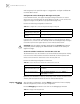
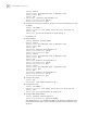
In actual network, we assume that the switches can intercommunicate.
Suppose that Host A is the receiver of the multicast group at 225.0.0.1. Host B
begins transmitting data destined to 225.0.0.1. LS_A receives the multicast data
from Host B via LS_B. When Host B transmits multicast data at the speed of
10kbps or higher, LS_A will be added to the SPT and receive the multicast packets
from Host B simply via LS_C.
Figure 11 PIM-SM Configuration Networking
Configure LS_A
1 Enable PIM-SM.
[SW7700] multicast routing-enable
[SW7700] vlan 10
[SW7700-vlan10] port Ethernet 1/0/2 to Ethernet 1/0/3
[SW7700-vlan10] quit
[SW7700] interface vlan-interface 10
[SW7700-vlan-interface10] pim sm
[SW7700-vlan-interface10] quit
[SW7700] vlan 11
[SW7700-vlan11] port Ethernet 1/0/4 to Ethernet 1/0/5
[SW7700-vlan11] quit
[SW7700] pim
[SW7700-pim] interface vlan-interface 11
[SW7700-vlan-interface11] pim sm
[SW7700-vlan-interface11] quit
Display the RP information display pim rp-info [ group-address ]
Enable the PIM-SM debugging debugging pim sm { all | mbr | register-proxy | mrt | timer
| warning | { recv | send } { assert | graft | graft-ack | join |
prune } }
Disable the PIM-SM
debugging
undo debugging pim sm { all | mbr | register-proxy | mrt |
timer | warning | { recv | send } { assert | graft | graft-ack |
join | prune } }
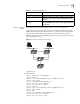
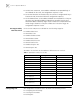
Table 31 Display and Debug PIM-SM
Operation Command
Host A Host B
VLAN12
VLAN10
VLAN10
VLAN11
VLAN11
VLAN12
VLAN10
VLAN12
VLAN11
LSD