
Switch 7700 Configuration Guide


SNMP 27
Example: SNMP
Configuration
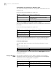
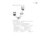
Network Management Station (NMS) and the Ethernet switch are connected via
the Ethernet. The IP address of NMS is 129.102.149.23 and that of the VLAN
interface on the switch is 129.102.0.1. Perform the following configurations on
the switch: setting the community name and access authority, administrator ID,
contact and switch location, and enabling the switch to sent trap packet.
Figure 5 SNMP Configuration Example
1 Enter the system view.
<SW7700> system-view
2 Set the community name and the access authority.
[SW7700] snmp-agent community read public
3 Set the administrator ID, contact and the physical location of the Ethernet switch.
[SW7700] snmp-agent sys-info contact Mr.Smith-Tel:3306
[SW7700] snmp-agent sys-info location telephone-closet, 3rd-floor
4 Enable SNMP agent to send the trap to NMS whose ip address is 129.102.149.23.
The SNMP community is public.
[SW7700] snmp-agent trap enable
[SW7700] snmp-agent target-host trap address udp-domain
129.102.149.23 udp-port 5000 params securityname public
Display the group name, the
security mode, the states for all
types of views, and the storage
mode of each group of the switch.
display snmp-agent group
Display the names of all users in the
group user table
display snmp-agent usm-user [ { local | { engineid
engineid } } | username groupname ]
Display the current community
name
display snmp-agent community [ read | write ]
Display the current MIB view display snmp-agent mib-view [ exclude | include | {
viewname mib-view } ]
Display the contact character string
of the system
display snmp-agent sys-info contact
Display the location character string
of the system
display snmp-agent sys-info location
Display the version character string
of the system
display snmp-agent sys-info version
Table 52 Display and Debug SNMP
Operation Command
NMS
129.102.149.23
129.102.0.1
Ethernet