
Switch 7700 Configuration Guide


54 CHAPTER 4: NETWORK PROTOCOL OPERATION
Example: Configuring
DHCP Relay
Configure the VLAN interface corresponding to the user and the related DHCP
server so as to use DHCP relay.
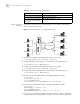
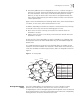
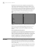
Figure 3 Networking Diagram of Configuring DHCP Relay
1 Configure the IP address corresponding to DHCP Server Group 1.
[3Com] dhcp-server 1 ip 1.99.255.36 1.99.255.35
2 Configure the DHCP Server Group 1 corresponding to the VLAN interface 2.
[3Com-VLAN-Interface2] dhcp-server 1
3 Configure the IP address corresponding to DHCP Server Group 2.
[3Com] dhcp-server 2 ip 1.88.255.36 1.88.255.35
4 Configure the DHCP Server Group 2 corresponding to the VLAN interface 3.
[3Com-VLAN-Interface3] dhcp-server 2
5 Configure the corresponding interface and gateway address of VLAN2.
[3Com] vlan 2
[3Com-vlan2] ❐❏❒▼ ✥▼❈❅❒■❅▼ ✑✏✐✏✒
[3Com] interface vlan 2
[3Com-VLAN-Interface2] ip address 1.1.2.1 255.255.0.0
6 Configure the corresponding interface and gateway address of VLAN3.
[3Com] vlan 3
[3Com-vlan3] port Ethernet 1/0/3
[3Com] interface vlan 3
[3Com-VLAN-Interface3] ip address 21.2.2.1 255.255.0.0
7 It is necessary to configure a VLAN for the server. However, in order to implement
the DHCP relay, the following example configures the servers with the same client
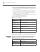
Enable the DHCP relay debugging debugging dhcp-relay
Disable the DHCP relay debugging undo debugging dhcp-relay
Display the address information of
all the legal clients of the DHCP
Server group.
display dhcp-security [ ip_address ]
Table 10 Displaying and Debugging DHCP Relay
Operation Command
VLAN 2
VLAN 3
VLAN
4000
VLAN
3001
Server 1
Server 2
1.99.255.36
1.99.255.35
1.88.255.36
1.88.255.35
IP Network