
Switch 7700 Configuration Guide


Static Routes 65
Example: Typical Static
Route Configuration
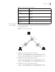
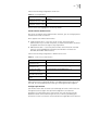
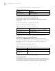
As shown in the Figure 3, the masks of all the IP addresses in the figure are
255.255.255.0. All the hosts or switches must be interconnected in pairs by
configuring static routes.
Figure 3 Static Route Configuration
1 Configure the static route for Ethernet Switch A:
[Switch A] ip route-static 1.1.3.0 255.255.255.0 1.1.2.2
[Switch A] ip route-static 1.1.4.0 255.255.255.0 1.1.2.2
[Switch A] ip route-static 1.1.5.0 255.255.255.0 1.1.2.2
2 Configure the static route for Ethernet Switch B:
[Switch B] ip route-static 1.1.2.0 255.255.255.0 1.1.3.1
[Switch B] ip route-static 1.1.5.0 255.255.255.0 1.1.3.1
[Switch B] ip route-static 1.1.1.0 255.255.255.0 1.1.3.1
3 Configure the static route for Ethernet Switch C:
[Switch C] ip route-static 1.1.1.0 255.255.255.0 1.1.2.1
[Switch C] ip route-static 1.1.4.0 255.255.255.0 1.1.3.2
view the route filtered through
specified basic access control
list (ACL)
display ip routing-table acl { acl-number | acl-name } [
verbose ]
view the route information
that through specified ip prefix
list
display ip routing-table ip-prefix ip-prefix-number [
verbose ]
View the routing information
found by the specified
protocol
display ip routing-table protocol protocol [ inactive |
verbose ]
View the tree routing table display ip routing-table radix
view the integrated routing
information
display ip routing-table statistics
Table 4 Display and Debug the Routing Table
Operation Command
A
B
C
Host 1.1.1.1
Host 1.1.4.2
Host 1.1.5.1
Switch A
Switch B
Switch C
1.1.1.2/24
1.1.2.1/24
1.1.5.2/24
1.1.3.1/24
1.1.3.2/24
1.1.4.1/24