Switch 7700 Installation Guide Version 3.0 3C16850 7-slot Starter Kit 3C16852 8-slot Starter Kit 3C16870 4-slot Starter Kit and associated modules http://www.3com.com/ Part No.
3Com Corporation 350 Campus Drive Marlborough, MA 01752-3064 Copyright © 2004, 3Com Corporation. All rights reserved. No part of this documentation may be reproduced in any form or by any means or used to make any derivative work (such as translation, transformation, or adaptation) without written permission from 3Com Corporation.
CONTENTS ABOUT THIS GUIDE Conventions 7 Related Documentation 8 SWITCH 7700 COMPONENTS Switch Chassis 9 Switch Backplane 9 Fabric Module 10 Submodule Slot 11 Reset Button 11 Fixed Ports 11 Module LEDs 12 Power LEDs 13 Fan LED 13 Fabric 32 Submodules 13 4-Port 1000BASE-X-GBIC Submodule 13 4-Port 10/100/1000BASE-T Submodule 14 I/O Modules 15 48-port 10/100BASE-T Auto-sensing FE Module 8-port 1000BASE-X GE Module 16 8-port 10/100/1000BASE-T GE Module 18 24-port 100BASE-FX MMF FE Module 19 20-Port 10/100/100
Installation Space 31 Installation Checklist 31 Installing the Chassis 32 Installing in a Standard Cabinet 32 Installing on a Workbench 32 Installing the Cabling Rack 32 Installing a Module 33 Installing a Submodule 33 Connecting the Ground Wire 34 Connecting and Configuring Power 34 Connecting AC Power Cords 34 Connecting DC Power Cords 35 Configuring AC Power Sources 35 Installing the Fan Assembly 36 Installing Cables 36 Connecting the Console Cable 36 Connecting the AUX Cable 36 Connecting Module Cables
Replacing a Power Supply 58 Replacing I/O Modules 59 Replacing the Fan Assembly 59 TROUBLESHOOTING Troubleshooting the Configuration 61 No information is displayed on the terminal The displayed characters are illegible 61 Troubleshooting Power 61 Troubleshooting the Fan 62 Troubleshooting the Modules 62 61 SWITCH 7700 CABLES Console Cable 63 AUX Cable 63 Electrical Port Connector 64 Optical Fiber Cable Connectors 65 OBTAINING SUPPORT FOR YOUR SWITCH Register Your Product to Gain Service Benefits Purcha
ABOUT THIS GUIDE This guide describes the 3Com® Switch 7700 and how to install hardware, configure and boot software, and maintain software and hardware. This guide also provides troubleshooting and support information for your switch. This guide is intended for Qualified Service personnel who are responsible for configuring, using, and managing the switches.
ABOUT THIS GUIDE Table 2 Text Conventions Convention Description Words in italics Italics are used to: Emphasize a point. Denote a new term at the place where it is defined in the text. Identify menu names, menu commands, and software button names. Examples: From the Help menu, select Contents. Click OK. Words in bold Related Documentation Boldface type is used to highlight command names. For example, “Use the display user-interface command to...
1 SWITCH 7700 COMPONENTS The chapter describes the following Switch 7700 components: Switch Chassis ■ Switch Chassis ■ Switch Backplane ■ Fabric Module ■ Fabric 32 Submodules ■ I/O Modules ■ Power Module ■ Fan Assembly ■ Switch 7700 Specifications ■ Switch 7700 Software Features There are three Switch 7700 Models, the 4-Slot, 7-Slot, and the 8-Slot. Table 3 lists the hardware features of each model.
CHAPTER 1: SWITCH 7700 COMPONENTS Fabric Module There are two Fabric modules for the Switch 7700: ■ Fabric 64 (3C16857 or 3C16857R) ■ Fabric 32 (3C16872) The Fabric 64 and Fabric 32 are not interchangeable. You can install the Fabric 32 only in a 4-slot chassis. You can install the Fabric 64 only in the 7- or 8-slot chassis The Fabric module is the core of Switch 7700 system.
Fabric Module 11 Table 4 lists Fabric specifications. Table 4 Fabric Specifications Item Fabric 64 (3C16857 or 3C16857R) Fabric 32 (3C16872) Bandwidth 64 Gbps CPU MPC8260 200 Mhz BootROM 1 MB SDRAM 256 MB Flash 16 MB 32 Gbps Submodule slot 1 Dimensions (L x W) 366.7 mm x 340 mm (14.5 x 13.5 in) External ports One console port that supports local and remote dial-up configuration management of the switch.
CHAPTER 1: SWITCH 7700 COMPONENTS Table 5 Console Port Specifications (continued) Specification Description Baud rate 9600 bps (by default) Transmission distance 15 m (45 ft) Services Connects with character terminal Connects with local or remote PC serial port and runs terminal emulation on a PC (a pair of modems are required for a remote connection) Ethernet Port The Ethernet port on the Fabric is connected to a computer using an RJ-45 connector.
Fabric 32 Submodules Power LEDs 13 PWR1, PWR2, and PWR3 LEDs show the status of the power modules, as described in Table 9. Table 9 Power LEDs Fan LED LED Description OK Green — The corresponding power module work is working normally. Off — The corresponding power module is not working or has not been installed. FAIL Green — The corresponding power module is not working. Off — The corresponding power module works normally or has not been installed.
CHAPTER 1: SWITCH 7700 COMPONENTS Table 12 lists the specifications for each of the 4-port 1000BASE-X-GBIC submodule. Table 12 4-Port 1000BASE-X-GBIC Submodule Specifications 4-Port 10/100/1000BASE-T Submodule Max. Transmission Distance Optional GBIC Module Central Wavelength Connector Type Interface Fiber Specifications 1000BASE-SX-MM (3CGBIC91) 850 nm SC 50/125 µm multi-mode fiber 62.
I/O Modules 15 See “Electrical Port Connector” on page 64 for an illustration of the RJ-45 connector and MDI/MDI-X pinout details. I/O Modules The Switch 7700 provides slots for three or six modules below the Fabric slots.
CHAPTER 1: SWITCH 7700 COMPONENTS 1 Ethernet port 2 Ethernet port LED Each 100 Mbps Ethernet port has a green LED, indicating LINK/ACTIVE status. Table 15 describes the 48-port 10/100BASE-T Auto-sensing FE module LED. Table 15 48-Port 10/100BASE-T Auto-sensing FE module LED LED Description LINK/ACT Green — The port is connected Off — The port is not connected Green flashing — Data is being transmitted Table 16 describes the specifications of the 48-port 10/100BASE-T Auto-sensing FE module.
I/O Modules 17 Figure 7 8-Port 1000BASE-X GE Module 8 685 3C1 Every GBIC port has a LED, as shown in Figure 8. Figure 8 Front Panel of the 8-Port 1000BASE-X GE Module 1 2 1 GBIC port 2 GBIC port LED Table 17 describes the 8-Port 1000BASE-X (GBIC) GE module LED.
CHAPTER 1: SWITCH 7700 COMPONENTS Table 19 Specifications for the 8-Port 1000BASE-X GE Module (continued) 8-port 10/100/1000BASE-T GE Module Specification Description BootROM 512 KB SDRAM 64 MB Dimensions (L x W) 366.7 x 340 mm (14.5 x 13.4 in) Maximum power consumption 50 W Number of ports 8 Optional GBIC module types 3CGBIC 91 3CGBIC 92 3CGBIC 97 Port transmission speed 1000 Mbps, full duplex Compliance IEEE 802.3z IEEE 802.
I/O Modules 19 Table 20 describes the LEDs on the 8-port 10/100/1000BASE-T GE module. Table 20 8-Port 10/100/1000BASE-T GE Module LEDs LED Description LINK Off — The link is not connected Green — The link is connected ACT Off — No data is being transmitted Green flashing — Data is being transmitted or received Specifications of the 8-port 10/100/1000BASE-T GE module are described in Table 21.
CHAPTER 1: SWITCH 7700 COMPONENTS Each 100 Mbps optical port has a green LED, as shown in Figure 12. Figure 12 Front Panel of the 24-Port 100BASE-FX MMF FE Module 1 2 1 Ethernet port 2 Ethernet port LED Table 22 describes the status of the 24-port 100BASE-FX MMF FE module LEDs. Table 22 24-Port 100BASE-FX MMF FE Module LEDs LED Description LINK/ACT Green — The port is connected. Off — The port is not connected. Green flashing — Data is being transmitted or received.
I/O Modules 21 Figure 13 20-Port 10/100/1000BASE-T Module 3C 16 86 3 Figure 14 illustrates the front panel of the 20-port 10/100/1000BASE-T module. Figure 14 Front Panel of the 20-Port 10/100/1000BASE-T Module 3C16863 1 2 1 Ethernet port 2 Ethernet port LED Table 24 describes the 20-port 10/100/1000BASE-T module LEDs. Table 24 20-Port 10/100/1000BASE-T Module LEDs LED Description LINK/ACT Off — The port is not operating. On — The port is operating.
CHAPTER 1: SWITCH 7700 COMPONENTS Table 25 Specifications for the 20-Port 10/100/1000BASE-T Module (continued) 20-Port 1000BASE-X-SFP Module Specification Description Cable and maximum transmission distance Category-5 twisted pair 100 m (300 ft) Compliance IEEE 802.3ab IEEE 802.3 IEEE 802.3u IEEE 802.3x IEEE 802.1D IEEE 802.1Q The 20-port 1000BASE-X-SFP module provides 20 1000 BASE-X full duplex ports and uses an SFP cable. Figure 15 illustrates the 20-port 1000BASE-X-SFP module.
I/O Modules 23 Table 27 lists specifications of the 20-port 1000BASE-X-SFP module. Table 27 Specifications for the 20-Port 1000BASE-X-SFP Module 1-Port 10GBASE-R-XENPAK Module Specification Description CPU MPC8241LZU200 BootROM 512 KB SDRAM 64 MB Dimensions (L x W) 366.7 x 340 mm (14.5 x 13.
CHAPTER 1: SWITCH 7700 COMPONENTS Table 28 describes the 1-port 10GBASE-R-XENPAK module LEDs. Table 28 1-Port 10GBASE-R-XENPAK Module LEDs LED Description LINK On — The port is operating Off — The port is not operating ACT Off — No data is being transmitted Green flashing — Data is being transmitted Table 29 lists specificatons of the 1-port 10GBASE-R-XENPAK module.
Fan Assembly 25 The 7- and 8-slot chassis also supports single- and dual-cord AC power module The dual-cord power module is available in two models for use with 110 V or 120 V AC current: ■ Single-cord — 3C16854 ■ Dual-cord 120 V model — 3C16892 ■ Dual-cord 220 V model — 3C16893 There are two models of the 8-slot chassis that offer either AC or DC power modules. Table 31 describes the specifications of each type of power module.
CHAPTER 1: SWITCH 7700 COMPONENTS Figure 19 Fan Assembly Switch 7700 Specifications Table 32 provides detailed information about features of the Switch 7700. Table 32 Specifications for the Switch 7700 System Item 4-Slot Chassis 7-Slot Chassis 8-Slot Chassis Dimensions (W x H x D) 436 x 352.8 x 480 mm 436 x 486.2 x 480 mm 436 x 530.
Switch 7700 Software Features Switch 7700 Software Features 27 Table 33 describes the software features of the Switch 7700. Table 33 Switch 7700 Software Features Service Support Wire speed Layer 2 switching Switching capacity of 64Gbps Packet forwarding rate at 48Mpps Wire speed forwarding (with forwarding delay less than 10µs) for I/O module ports Port auto-negotiation Speed and duplex operation modes.
CHAPTER 1: SWITCH 7700 COMPONENTS Table 33 Switch 7700 Software Features (continued) Service Support Load and upgrade system Xmodem protocol software FTP and TFTP
2 INSTALLING THE SWITCH 7700 The following sections describe how to prepare and install the components of the Switch 7700: ■ Preparing to Install ■ General Site Requirements ■ Installation Checklist ■ Installing the Chassis ■ Installing the Cabling Rack ■ Installing a Module ■ Installing a Submodule ■ Connecting the Ground Wire ■ Connecting and Configuring Power ■ Installing the Fan Assembly ■ Installing Cables ■ Connecting Module Cables ■ Post-installation Checklist WARNING: Onl
CHAPTER 2: INSTALLING THE SWITCH 7700 ■ During the installation, wear an antistatic wrist strap and antistatic gloves. See “Static Electricity” on page 31 for additional information on preventing static. WARNING: Follow local safety regulations when performing any operation with the Switch 7700. Follow the related safety information and special safety instructions provided by 3Com. 3Com bears no responsibility for accidents that occur due to violations of safe operation requirements.
Installation Checklist 31 Table 34 Temperature and Humidity Requirements Temperature 00 to 400C (320 Relative humidity (noncondensing) to 1040F) 10% to 90% Static Electricity To prevent damage caused by the static electricity, ensure that: ■ The equipment is grounded ■ The equipment room is dust-proof ■ Adequate temperature and humidity conditions are maintained. ■ The operator wears an antistatic wrist strapwhile handling the module.
CHAPTER 2: INSTALLING THE SWITCH 7700 ■ ■ ■ Tools ■ Phillips screwdriver ■ Flat-head screwdriver ■ Antistatic wrist strap Cables ■ Console cable ■ AUX cable ■ Power cord and chassis ground wire ■ Interface cables for the selected interface modules Equipment ■ The switch ■ Ethernet 100BASE-T Hub or LAN switch ■ Installing the Chassis Installing in a Standard Cabinet Channel service unit/data service unit (CSU/DSU) or other data communications equipment (DCE) equipment (such as a m
Installing a Module Installing a Module 33 To install a module: 1 Wear an antistatic wrist strap. 2 Remove the blanking plate from the chassis slot and save it for future use. 3 Hold the ejector levers of the module with both hands and push them outward. 4 Align the module with the guides in the chassis and slide it gently into the slot. 5 Push the module until the captive thumb screw on its handle bar touches the hole in the chassis.
CHAPTER 2: INSTALLING THE SWITCH 7700 Connecting the Ground Wire To connect the ground wire: 1 Wear an antistatic wrist strap. 2 Remove the screw from the grounding hole in the switch chassis. 3 Set the ground wire connector around the grounding screw. 4 Fasten the grounding screw in the hole on the chassis. 5 Connect the other end of the ground wire to the grounding bar of the switch.
Connecting and Configuring Power Connecting DC Power Cords 35 To connect DC power cords, do the following: 1 Power off all the related parts of the switch when connecting the DC power cord. 2 Loosen the mounting screw and remove the cover of the connection terminals on the DC power distribution box. 3 Loosen the mounting nut of the connection terminal, using a socket wrench.
CHAPTER 2: INSTALLING THE SWITCH 7700 Installing the Fan Assembly To install the fan: 1 Wear an antistatic wrist strap. 2 Remove the fan frame from the pack. 3 Hold the ejector levers on the fan frame with both hands and push them outward. 4 Align the fan with the guides in the chassis and slide it gently into the slot. 5 Push the fan until its positioning pin touches the hole in the chassis. 6 Push the ejector levers inward. 7 Push the handle bar pin into the hole in the chassis.
Installing Cables Connecting Module Cables 37 This section describes how to connect electrical and optical cables. Connecting Electrical Port Cables The 48-port 10/100BASE-T module and 8-port 10/100/1000BASE-T module require a RJ-45 connector and category-5 twisted pair cable. See “Electrical Port Connector” on page 64 for an illustration of the RJ-45 connector and MDI/MDI-X pinout details.
CHAPTER 2: INSTALLING THE SWITCH 7700 CAUTION: When connecting an SC fiber connector, the switch TX must be connected to the RX of the device on the network, and the switch RX must be connected to the TX of the device on the network. MT-RJ fiber connector The 24-port 100BASE-FX MMF FE module requires an MT-RJ optical fiber connector. To attach the MT-RJ fiber connector: 1 Plug the MT-RJ fiber connector in the optical port into the module.
Post-installation Checklist 39 Follow the parameters defined in Table 35 for binding cables with ties. Table 35 Cable Binding Parameters Post-installation Checklist Cable Bundle Diameter Space Between Bundles 10 mm (0.5in) 80-150 mm (3.5 – 6 in) 10-30 mm (.5 – 1.2 in) 150-200 mm (6 – 8 in) 30 mm (1.2 in) 200-300 mm (8 – 12 in) After you install your switch, use the checklist in Table 36 to verify that your switch operates correctly.
CHAPTER 2: INSTALLING THE SWITCH 7700
3 CONFIGURING THE SWITCH 7700 The following sections of this chapter describe how to configure and boot the Switch 7700: Configuring the Switch 7700 and a Local Terminal ■ Configuring the Switch 7700 and a Local Terminal ■ Setting Terminal Parameters ■ Booting the Switch 7700 Configure the local terminal and Switch 7700, using Figure 22 as a reference. The terminal (a PC in this example) is connected to the switch console port using a console cable.
CHAPTER 3: CONFIGURING THE SWITCH 7700 Figure 23 Connection Description Dialog Box 2 Enter the name of the new connection in the Name field and click OK. The dialog box, shown in Figure 24 displays. Select the serial port to be used from the Connect using dropdown menu. Figure 24 Properties Dialog Box 3 After selecting serial ports, click OK. The port shown in Figure 25 displays and you can set serial port parameters.
Setting Terminal Parameters Figure 25 COM1 Properties Dialog Box 4 Click OK. The HyperTerminal dialogue box displays, as shown in Figure 26. Figure 26 HyperTerminal Window 5 Select Properties. 6 In the Properties dialog box, select the Settings tab, shown in Figure 27. 7 Select VT100 in the Emulation dropdown menu. 8 Click OK.
CHAPTER 3: CONFIGURING THE SWITCH 7700 Figure 27 Settings Tab Booting the Switch 7700 Before powering on the Switch 7700, verify that: ■ Power cords have been properly connected. ■ The voltage of power supply can meet the requirements on the switch. ■ The console cable has been connected properly. ■ The PC or terminal for configuration has been started. ■ The terminal parameters have been set.
Booting the Switch 7700 Powering up and Booting 45 Turn on the power for the Switch 7700 and run the BootROM program. The terminal displays the following information: Starting...... RAM Line....OK System is booting..................... ****************************************** * * * Switch 7700 BOOTROM, Version 300 * * * ****************************************** Copyright(C) 2001-2005 by 3Com Corporation, Inc.
CHAPTER 3: CONFIGURING THE SWITCH 7700 The display of these messages indicates the completion of the switch auto-booting. Press Enter and the terminal screen displays: <3Com> You can now begin the configuration for the Switch 7700.
4 MAINTAINING SOFTWARE This chapter covers the following topics: Upgrading Software ■ Upgrading Software ■ Lost Passwords ■ Using the BOOT Menu The following sections describe how to upgrade software on your Switch 7700: ■ Upgrading the Software Image ■ Upgrading an 8-Slot Chassis ■ Upgrading Software with FTP ■ Upgrading Software Using The BOOT Menu ■ Upgrading Software Using Xmodem ■ Upgrading Software Using TFTP Always save the configuration file before upgrading applications.
CHAPTER 4: MAINTAINING SOFTWARE To upgrade an 8-slot Switch 7700 with FTP: 1 Upgrade the Fabric in Slot0 using the procedure in Upgrading Software with FTP. Do not issue the reboot command. 2 Execute the slave switchover command on Slot0 so that the Fabric in Slot1 becomes the primary Fabric. 3 Repeat Step 1 for Slot1. 4 Issue the reboot command and enter Y at the reboot prompt so the system reboots. As the system reboots, the Fabric in Slot0 will return to primary status.
Upgrading Software 49 boot boot-loader sw7700003.app The specified file will be booted next time! reboot This will reboot Switch. Continue? [Y/N] y For more detailed descriptions of the setup and procedures for upgrading software, see the remaining sections in this chapter. Upgrading Software Using The BOOT Menu To perform this procedure, you must have a network connection to the management port on the Switch 7700 Fabric module.
CHAPTER 4: MAINTAINING SOFTWARE 2: Select application file to boot 3: Display all files in flash 4: Delete file from flash 5: Modify bootrom password 0: Reboot Enter your choice(0-5): Downloading an Application to Flash Memory To download an application to flash memory: 1 Select option 1 on the Boot Menu. The following menu displays: 1. Set TFTP protocol parameter 2. Set FTP protocol parameter 3. Set XMODEM protocol parameter 0.
Upgrading Software 10. 199696 11. 2427 12. 203460 lpcom400.app 13. 228308 snec400.app 51 8241btm.app vrpcfg.txt The current application file is :SW7700-V300R-.app The backup application file is :SW7700-V300RE-8016.app Free Space : 7536640 bytes 2 Enter the file number of the primary image: Please input the primary image file number :13 3 To confirm this choice, type Y at the prompt: The file you selected is snec400.app, are you sure? Yes or No(Y/N) Y On reboot,snec400.
CHAPTER 4: MAINTAINING SOFTWARE There is one passed image in addition: File Number File Size(bytes) File Name ======================================================== 1. 6256229 SW7700-V300RE-8016.app Press Ctrl+B to enter Boot Menu... 0 Auto-booting.................... Auto booting file is snec400.app No LPU application file < vxworks.app > in flash Please download LPU application file vxworks.
Upgrading Software 53 Starting at 0x60000... The primary image name is saved in flash memory, the secondary image name is saved in the EPPROM. However, if you use the display boot command to display the boot image it will only read from flash so only the primary image will be displayed. The secondary boot image name cannot be displayed when there is an image error. Upgrading Software Using Xmodem The Xmodem protocol transmits files through serial ports and supports both 128-byte and 1K-byte packets.
CHAPTER 4: MAINTAINING SOFTWARE 7 Change the baud rate set at the configuration terminal, so that the baud rate is consistent with the selected download baud rate of the software. 8 Disconnect the terminal and reconnect it. 9 Press Enter to start downloading. The terminal displays the following information: Now please start transfer file with XMODEM protocol. If you want to exit, Press . Waiting ... CCCCC 10 Select Transfer\Send File from the terminal window.
Lost Passwords Upgrading Software Using TFTP 55 TFTP (Trivial File Transfer Protocol) is a simple file transfer protocol that is used without complex interaction between clients and servers. The client initiates a TFTP transmission. To download files, the client sends a read request packet to the TFTP server, receives the packet from the server, and sends the acknowledgement to the server.
CHAPTER 4: MAINTAINING SOFTWARE RAM Line....OK System is booting................ * * • SW 7700 BOOTROM, Version 4.00 * * * Copyright© 2001-2005 by 3Com Corporation, Inc. Creation date : May 26 2002, 10:23:31 CPU type : MPC8260 CPU Clock Speed : 200MHz BUS Clock Speed : 66MHz Memory Size : 128MB SW 7700 main board self testing............................... 60X_SDRAM Data lines Selftest.............................OK! 60X_SDRAM Address lines Selftest..........................OK! 60X_SDRAM fast selftest.
5 MAINTAINING HARDWARE This chapter covers the following topics: ■ Replacing a Power Module ■ Replacing a Power Supply ■ Replacing I/O Modules ■ Replacing the Fan Assembly The procedures in this chapter should be performed by trained service personnel only. Replacing a Power Module The single-cord power module in the 7- and 8-slot AC chassis of the Switch 7700 can be upgraded to a dual-power cord module.
CHAPTER 5: MAINTAINING HARDWARE 4 Tighten the retaining screw on the lower right front of the power supply. 5 Connect 2 power cords to the power module. 6 Connect the power cords to separate AC power sources on separate power grids or to a UPS/backup power system. WARNING: Do not power on the switch until you reconnect all the components.
Replacing I/O Modules 59 CAUTION: Do not clean the filter while it is in position at the front of the power supply. Attempts to do so could result in damage to the equipment or severe electrical shock. Replacing I/O Modules To replace an I/O module, you need: ■ An antistatic wrist strap ■ A Screwdriver To remove a module: 1 Remove all the cables from the module to be removed. 2 Loosen the captive screws.
CHAPTER 5: MAINTAINING HARDWARE 4 With both hands, pull out the ejector levers of the fan that will be installed. Align it with the guides in the chassis and slide it gently into the slot until you feel the positioning pin on the handle bar touch the hole in the chassis. 5 Press the ejector levers inward and seat the pin on the handle bar into the positioning hole in the chassis. WARNING: If the fan fails, replace it with a new one without delay before operating the Switch 7700.
6 TROUBLESHOOTING This chapter covers the following topics: ■ Troubleshooting the Configuration ■ Troubleshooting Power ■ Troubleshooting the Fan ■ Troubleshooting the Modules The simplest way to diagnose a fault is to check the system status LEDs on the Fabric modules. In addition, with the DeviceMgr network management system, you can also locate the fault through management software.
CHAPTER 6: TROUBLESHOOTING Table 37 describes power LEDs on the Fabric. (continued) Table 37 Power LEDs on the Fabric Troubleshooting the Fan LED Status Description OK On — The power is working normally. Off — The power has failed or has not been installed. FAIL On — The power has failed. Off — The power is working normally or has not been installed. If the fan OK LED is off, check that: ■ The fan has been installed in the correct position for normal communication with the backplane.
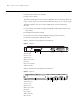
A SWITCH 7700 CABLES This appendix covers the following types of cables and connectors: Console Cable ■ Console Cable ■ AUX Cable ■ Electrical Port Connector ■ Optical Fiber Cable Connectors Figure 30 illustrates the console cable and connectors. Figure 30 The Console cable Enlarged A side DB25 Female 8P8C Plug Enlarged B side DB9 Female Enlarged C side Table 40 lists console cable pin-outs.
APPENDIX A: SWITCH 7700 CABLES Figure 31 The AUX Cable Enlarged A side DB25 Male 8P8C Plug Label Enlarged B side DB9Male Enlarged C side Table 41 lists the AUX cable pin-outs. Table 41 AUX Cable Pin-outs Electrical Port Connector RJ-45 Signal Direction DB-25 DB-9 1 RTS ---> 4 7 2 DTR ---> 20 4 3 TXD ---> 2 3 4 CD <--- 8 1 5 GND --- 7 5 6 RXD <--- 3 2 7 DSR <--- 6 6 8 CTS <--- 5 8 Figure 32 illustrates the RJ-45 connector.
Optical Fiber Cable Connectors Table 42 RJ-45 MDI Port Pin-outs (continued) Pinout 10BASE-T/100BASE-TX 1000BASE-T 3 Rx+ Receive data BIDB+ Send data to direction B 4 Reserved - BIDC+ Receive data from direction C 5 Reserved - BIDC- Send data to direction C 6 Rx- Receive data BIDB- Receive data from direction B 7 Reserved - BIDD+ Send data to direction D 8 Reserved - BIDD- Receive data from direction D Tx = Send data Rx = Receive data BI = I-directional data.
APPENDIX A: SWITCH 7700 CABLES Figure 34. illustrates the MT-RJ fiber optic cable connector. Figure 34 The MT-RJ Fiber Connector Figure 35 illustrates the LC connector.
B OBTAINING SUPPORT FOR YOUR SWITCH Register Your Product to Gain Service Benefits To take advantage of warranty and other service benefits, you must first register your product at http://eSupport.3com.com/. 3Com eSupport services are based on accounts that you create or have authorization to access. First time users must apply for a user name and password that provides access to a number of eSupport features including Product Registration, Repair Services, and Service Request.
APPENDIX B: OBTAINING SUPPORT FOR YOUR SWITCH Software Upgrades are the software releases that follow the software version included with your original product. In order to access upgrades and related documentation you must first purchase a service contract from 3Com or your reseller. Contact Us 3Com offers telephone, e-mail and internet access to technical support and repair services.
Telephone Technical Support and Repair Country Telephone Number Country Telephone Number Europe, Middle East, and Africa Telephone Technical Support and Repair From anywhere in these regions, call: +44 (0)1442 435529 From the following countries, you may use the numbers shown: Austria Belgium Denmark Finland France Germany Hungary Ireland Israel Italy 01 7956 7124 070 700 770 7010 7289 01080 2783 0825 809 622 01805 404 747 06800 12813 01407 3387 1800 945 3794 199 161346 Luxembourg Netherlands Norwa
APPENDIX B: OBTAINING SUPPORT FOR YOUR SWITCH