
Switch 7700 Installation Guide

16 CHAPTER 1: SWITCH 7700 COMPONENTS
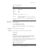
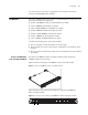
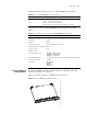
1 Ethernet port
2 Ethernet port LED
Each 100 Mbps Ethernet port has a green LED, indicating LINK/ACTIVE status.
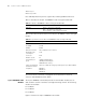
Table 15 describes the 48-port 10/100BASE-T Auto-sensing FE module LED.
Table 16 describes the specifications of the 48-port 10/100BASE-T Auto-sensing FE
module.
See “Electrical Port Connector” on page 64 for an illustration of the RJ-45
connector and MDI/MDI-X pinout details.
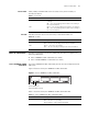
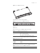
8-port 1000BASE-X GE
Module
The 8-port 1000BASE-X GE module provides 8 external GBIC module ports. A
GBIC module is used for each data receiving/transmitting channel. The following
modules are available:
■ 3CGBIC91
■ 3CGBIC92
■ 3CGBIC97
Figure 7 illustrates the 8-port 1000BASE-X GE module.
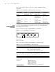
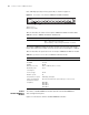
Tabl e 15 48-Port 10/100BASE-T Auto-sensing FE module LED
LED Description
LINK/ACT Green — The port is connected
Off — The port is not connected
Green flashing — Data is being transmitted
Tabl e 16 Specifications for the 48-Port 10/100BASE-T Auto-sensing FE Module
Specification Description
CPU MPC850
BootROM 512 KB
SDRAM 64 MB
Dimensions (L X W) 366.7 x 340 mm (14.5 x 13.4 in)
Maximum power
consumption
55 W
Connector RJ-45
Number of ports 48
Port transmission
speed
10 Mbps half/full duplex
100 Mbps half/full duplex
MDI/MDIX auto-sensing
Cables and maximum
transmission distance
Cables are 2 100-ohm Category-5 twisted pairs up to 100 m (300 ft).
Compliance IEEE802.3
IEEE802.3u
IEEE802.3x