
Switch 7700 Installation Guide

20 CHAPTER 1: SWITCH 7700 COMPONENTS
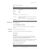
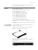
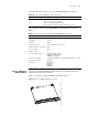
Each 100 Mbps optical port has a green LED, as shown in Figure 12.
Figure 12 Front Panel of the 24-Port 100BASE-FX MMF FE Module
1 Ethernet port
2 Ethernet port LED
Table 22 describes the status of the 24-port 100BASE-FX MMF FE module LEDs.
The 24-port 100BASE-FX MMF FE module requires a 62.5/125 µm multi-mode
optical fiber cable with an MT-RJ connector and a central wavelength of 1300 nm.
Table 23 describes the specifications of the 24-port 100BASE-FX MMF FE module.
20-Port
10/100/1000BASE-T
Module
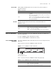
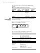
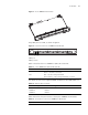
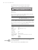
The 20-Port 10/100/1000BASE-T module provides 20 10/100/1000BASE-T
auto-sensing Ethernet ports.
Figure 13 illustrates the 20-Port 10/100/1000BASE-T Module.
Tabl e 22 24-Port 100BASE-FX MMF FE Module LEDs
LED Description
LINK/ACT Green — The port is connected.
Off — The port is not connected.
Green flashing — Data is being transmitted or received.
Tabl e 23 Specifications for the 24-Port 100BASE-FX MMF FE Module
Specification Description
CPU MPC850
BootROM 512 KB
SDRAM 64 MB
Dimensions (L x W) 366.7 x 340 mm (14.5 x 13.4 in)
Maximum power
consumption
55 W
Connector type MT-RJ
Number of ports 24
Port transmission speed 100 Mbps, full-duplex
Cables and maximum
transmission distance
62.5/125 µm multi-mode optical fiber up to 2 km (1.3 mi)
Compliance IEEE 802.3
IEEE 802.3i
IEEE 802.3u
IEEE 802.3x
1
2