
Switch 7700 Installation Guide


24 CHAPTER 1: SWITCH 7700 COMPONENTS
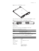
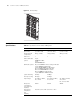
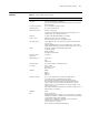
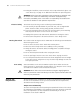
Table 28 describes the 1-port 10GBASE-R-XENPAK module LEDs.
Table 29 lists specificatons of the 1-port 10GBASE-R-XENPAK module.
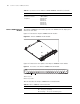
Power Module Only one AC power module is required for the 4-slot chassis although 2 power
module slots are provided to implement N+1 redundancy.
Table 31 describes the
specifications of the power module for the 4-slot chassis.
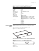
The 7-slot and 8-slot chassis provides three power module slots to implement N+1
redundancy. However, two power modules are sufficient to power one of these
fully loaded Switch 7700 systems.
Tabl e 28 1-Port 10GBASE-R-XENPAK Module LEDs
LED Description
LINK On — The port is operating
Off — The port is not operating
ACT Off — No data is being transmitted
Green flashing — Data is being transmitted
Tabl e 29 Specifications for the 1-Port 10GBASE-R-XENPAK Module
Specification Description
CPU MPC8245
BootROM 512 KB
SDRAM 64 MB
Dimensions (L x W) 366.7 x 340 mm (14.5 x 13.4 in)
Power consumption 35 W
Connector SC
Number of ports 1
Transmission rate 10 Gbps full duplex
Cable and maximum
transmission distance
10GBASE-LR-XENPAK (single mode optical fiber, 1310 nm 10 km)
10GBASE-ER-XENPAK (single mode optical fiber, 1550 nm 40 km)
Compliance IEEE 802.1p
IEEE 802.1Q
IEEE 802.1D
IEEE 802.3
IEEE 802.3u
IEEE 802.3x
IEEE 802.3ad
IEEE 802.3ae
Tabl e 30 Specifications for the 4-Slot Chassis Power Modules
Specification
AC Power Module
(4-slot chassis)
Input 100 V to 240 V, 47 to 63 Hz
Maximum output 350 W
Lightening protection Lightening protection circuit of the AC power socket