
Switch 7700 Installation Guide


34 CHAPTER 2: INSTALLING THE SWITCH 7700
Connecting the
Ground Wire
To connect the ground wire:
1 Wear an antistatic wrist strap.
2 Remove the screw from the grounding hole in the switch chassis.
3 Set the ground wire connector around the grounding screw.
4 Fasten the grounding screw in the hole on the chassis.
5 Connect the other end of the ground wire to the grounding bar of the switch.
If you install the switch in a cabinet, 3Com recommends that the ground wire of
the switch be connected to the grounding bar of the cabinet.
WARNING: The resistance between switch chassis and the ground should be less
than 1 ohm.
Connecting and
Configuring Power
The 7-slot and 8-slot chassis offers power modules with one or two power cords.
The power module in the 4-slot chassis has two power cords.
In addition, the 8-slot chassis is available with either AC or DC power modules.
Connecting AC Power
Cords
To connect AC power cords:
1 Power off all the related parts of the switch before connecting the AC power cord
2 Plug the power cord into the socket in the switch and attach the retention clip to
the power cord plug.
3 Plug the other end of the cord into a socket strip with surge protector. Connect
the strip to the power source in the room.
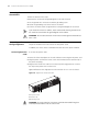
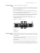
Figure 20 illustrates the single power cord connection for a 7- or 8-slot chassis.
Figure 20 Single Power Cord Connection
1 AC power socket
2 Retention clip
3 Grounding screw
WARNING: For surge protection, the power should be channelled through an
external protection device into the Switch 7700.
213