HP 7500-CMW520-R6708 Release Notes © Copyright 2013 Hewlett-Packard Development Company, L.P. The information contained herein is subject to change without notice. The only warranties for HP products and services are set forth in the express warranty statements accompanying such products and services. Nothing herein should be construed as constituting an additional warranty. HP shall not be liable for technical or editorial errors or omissions contained herein.
Contents Version information·························································································································································· 1 Version number ································································································································································· 1 Version history ····································································································································
Contacting HP ································································································································································17 Subscription service ······················································································································································· 17 Appendix A Feature list ·······································································································································
List of Tables Table 1 Version history ................................................................................................................. 1 Table 2 HP 7500 product family matrix ........................................................................................... 2 Table 3 Hardware and software compatibility matrix ........................................................................ 3 Table 4 ISSU Compatibility matrix .................................................................
This document describes the features, restrictions and guidelines, open problems, and workarounds for version R6708 & R6708-US. In the interest of brevity, any reference to R6708 is also applicable to R6708-US for the remainder of this document. Before you use this version in a live network, back up the configuration and test the version to avoid software upgrade affecting your live network.
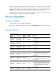
Version number Last version Release date Release type Remarks 7500-CMW5 20-R6635 7500-CMW52 0- F6632 2011-1220 Release Fixes bugs 7500-CMW5 20-F6632 7500-CMW52 0- F6630 2011-1130 Feature Fixes bugs 7500-CMW5 20-F6630 7500-CMW52 0- R6626 2011-0915 Feature New Feature: critical VLAN Fixes bugs 7500-CMW5 20-R6626 S7500E-CMW 520-R6616P0 5 2011-0711 New Release Fixes bugs S7500E-CM W520-R6616 P05 S7500E-CMW 520-R6616P0 2 2011-0503 None Fixes bugs S7500E-CM W520-R6616 P02
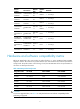
Table 3 Hardware and software compatibility matrix Item Specifications Product family HP 7500 series, 3Com S7900E series and H3C S7500E series HP 7502/7503-S/7503/7506/7506-V/7510 3Com S7902E/S7903E/S7906E/S7906E-V/S7910E Hardware platform H3C S7502E/S7503E-S/S7503E/S7506E/S7506E-V/S7510E Minimum memory requirements 512M Minimum Flash requirements 64M Shipped with the switch. Boot ROM image (Use the display version command in any view to view the BootRom version.
Bootrom Version: 301 CPLD 1 Version: 002 CPLD 2 Version: 002 Release Version: HP 7503-6708 Patch Version None : ------Note② Slot 1 Without Board Slot 2 Without Board LPU 3: Uptime is 0 weeks,0 days,8 hours,18 minutes HP 7503 LPU with 1 BCM1122 Processor BOARD TYPE: LSQ1GV48SC DRAM: 512M bytes FLASH: 0M bytes NVRAM: 0K bytes PCB 1 Version: VER.
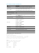
Hardware feature updates 7500-CMW520-R6708 R6708 supports the following new hardware: None 7500-CMW520-F6707L02 F6707L02 supports the following new hardware: None 7500-CMW520-F6705L01 F6705L01 supports the following new hardware: None 7500-CMW520-R6703 R6703 supports the following new hardware: JC792A HP 7500 4-port 40GbE QSFP+ SC Module JG373A HP 7500 4-port 40GbE CFP SC Module 7500-CMW520-F6702 F6702 supports the following new hardware: None 7500-CMW520-R6701 R6701 supports the fol
JD242B HP 7502 Switch Chassis JD243B HP 7503 Switch Chassis w/1 Fabric Slot JD197B HP 7500 48-port 100Base-FX SA Module JD198B HP 7500 48-port 10/100Base-TX PoE-upgradable SA Module JD199C/JD199B JC667A HP 7500 16-port GbE SFP / 8-port GbE Combo SA Module JC668A HP 7500 20-port Gig-T / 4-port GbE PoE-upgradable Combo SA Module JD201A HP 7500 2-port 10-GbE XFP SC Module JD203B HP 7500 24-port GbE SFP SC Module JC704A HP 7500 24-port GbE SFP SC TAA-compliant Module J
JC716A HP 7500 4-port 10-GbE XFP EB TAA-compliant Module JD233A HP 7500 2-port 10-GbE XFP EB Module Software feature and command updates For more information about the software feature and command update history, see HP 7500-CMW520-R6708 Release Notes (Software Feature Changes).
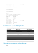
Item MIB file Module Description entPhysicalMod elName hh3c-entity-vendortype-oid .mib ENTITY-MIB Removing "A" from 7500 entPhysicalVend orType hh3c-entity-vendortype-oid .mib ENTITY-MIB Removing "A" from 7500 hh3cLswSlotSoft wareVersion hh3c-lsw-dev-adm.
3. The hp 7500 product family supports four IRF members in R6635. There are several setup and configuration limitation, please check the Command Line Manual and Operation Manual of new release for detail. 4. If you enable multicast ARP and connect the device to an NLB server through an aggregate interface, any port that receives client traffic must not reside on the same card as any member port of the aggregate interface. Open problems and workarounds LSD68672 Symptom: The IRF fabric may split.
Condition: This symptom occurs if a packet matches two entries in the PBR policy LSD074042 Symptom: Walking the entPhysicalVendorType MIB fails to get the transceiver information on the Combo interfaces. Condition: This symptom can be seen during a walk on the entPhysicalVendorType MIB. LSD074025 Symptom: The CPU usage on the 40G card is high when the switch operates normally. Condition: This symptom might be seen when the switch operates normally.
Resolved problems in F6705L01 LSD072942 Symptom: By default, some TCP/UDP ports, such as RADIUS, are in Listening state, need to be closed. Condition: The device starts up with default configuration. Resolved problems in F6705 LSD68133 Symptom: In this version of code, the password encryption within configuration files has been enhanced and cannot be interpreted by earlier revisions of the agent code. More details please reference HP 7500-CMW520-F6705 Release Notes (Software Feature Changes).
LSD071729 Symptom: The subordinate device in an IRF fabric reboots. Condition: This symptom might occur if undo vsi is executed when the state of the peer is changing. LSD071750 Symptom: IMC cannot show the panel of the switch. Condition: This symptom occurs when IMC accesses the switch. LSD071724 Symptom: Track fails to work when PBR needs to perform a nexthop failover. Condition: This symptom might occur if the following conditions exist: PBR has more than two nodes.
LSD070621 Symptom: OSPF calculation occupies too many CPU resources when flooding occurs because of LSA aging. Condition: This symptom might occur in an OSPF network where large numbers of routes and OSPF neighbors exist and NSR is enabled. LSD070593 Symptom: The private MIB OID value is 25506(HP), and it should be replaced with 6296(Dasan). Condition: Read the MIB tree of a Dasan device. Resolved problems in R6701 LSD68827 Symptom: MPLS works abnormally.
LSD62656 Symptom: BGP neighbors are not stable. Condition: When the CPU is highly occupied. LSD63920 Symptom: the LLDP neighbor’s information is wrong. Condition: When the LLDP packets whose LCI value in location ID TLV is zero enter the device. LSD66072 Symptom: Non-compatible transceiver module will be invalidated in 30 days. Condition: Using Non-compatible transceiver module.
Resolved problems in R6626 LSD62272 Symptom: RRPP fails to operate when the RRPP control VLAN ID is identical with the sub interface VLAN ID. Condition: When the RRPP control VLAN ID is identical with the sub interface VLAN ID. LSD62435 Symptom: A sub interface fails to forward traffic to another chassis when its VLAN ID is identical with the MAD VLAN ID. Condition: When sub interface’s VLAN ID is identical with the MAD VLAN ID.
Resolved problems in R6616P02 LSD55210 Symptom: Sometimes IP packets will fail to be forwarded. Condition: When configured the IP FRR function. Resolved problems in R6616P01 LSD53884 Symptom: Sometimes a wrong Multi-Active Detection will occur. Condition: When rebooting one chassis with the LSQ1SRP2XB 10GE ports as IRF ports. LSD53222 Symptom: Sometimes in portal stateful failover function, LSQ1SPRD master card cannot establish the failover link with the other device. Condition: None.
Related documentation Documentation set HP 7500 Switch Series Installation Guide HP 7500 Switch Series Configuration Guides (R6700 series) HP 7500 Switch Series Command References (R6700 series) Obtaining documentation To find related documents, browse to the Manuals page of the HP Business Support Center website: http://www.hp.com/support/manuals Contacting HP For worldwide technical support information, see the HP support website: http://www.hp.
Appendix A Feature list Hardware features Table 6 HP 7500 series hardware features Item Specification HP 7502: 175 x 436 x 420 mm (6.89 x 17.17 x 16.54 in.) HP 7503-S: 175 x 436 x 420 mm (6.89 x 17.17 x 16.54 in.) Dimensions (H × W × D) (excluding feet and rack-mounting brackets) HP 7503: 441.7 x 436 x 420mm (17.39 x 17.17 x 16.54 in.) HP 7506: 575.05 x436 x 420mm (22.64 x 17.17 x 16.54 in.) HP 7506-V: 930.6 x 436 x 420mm (36.64 x 17.17 x 16.54 in.)) HP 7510: 708.4 x 436 x 420mm (27.89 x 17.17 x 16.
Item Specification 6 slots (HP 7506-V) 10 slots (HP 7510) Software features Table 7 Software features of the HP 7500 series Category Features Ethernet II IEEE 802.3/802.2 SNAP IEEE 802.3/802.2 Long Frame (1518-1536) Jumbo Frame (1536-9216) VLAN (Port-based VLAN/Subnet-based VLAN/Protocol-based VLAN/Mac-based VLAN) IEEE 802.1Q Layer 2 IEEE802.1p RSTP(802.1w) MSTP(802.1s) LACP(802.
Category Features Static route management RIP OSPF BGP IS-IS Policy based routing IPv6 routing: IPv6 static route management RIPng OSPFv3 BGP+ IS-ISv6 IGMP Snooping IGMP MLD Snooping MLD Multicast PIM-DM PIM-SM PIM-SSM BIDIR-PIM MSDP Remark 802.1p, DSCP, IP precedence, or local precedence by ACL rule Map to output queue by 802.
Category Features NetStream RMON Public MIBs Private MIBs Syslog/Debug IMC CLI Local management File management Dual-image Console login AUX login User access control Telnet (VTY) login SSH login FTP login XMODEM Ping DNS client DHCP server DHCP client DHCP relay agent Application protocols DHCP snooping Telnet FTP client FTP server TFTP client NTP client/server VRRP Availability Dual fabric IRF ISSU RADIUS TACACS+ Security EAD Portal 802.
22
Appendix B Software Upgrade Software used for upgrade Boot ROM images Boot ROM images are used to upgrade the Boot ROM program of cards, including the main processing units (MPUs) and line processing units (LPUs). A Boot ROM image is a .btw file. System software images System software images are used at switch startup. The HP 7500 series support two types of system software image: Main system software image—The default system software image a switch uses for startup.
NOTE: HP recommends you to upgrade software from the CLI when your switch operates normally. To ensure that the active and standby MPUs use the same software version, upgrade them by using the same method. Make sure the system software and Boot ROM are compatible. For the compatibility between the system software and Boot ROM, see the hardware and software compatibility matrix in the Release Notes. You can upgrade the Boot ROM for the LPUs from the CLI only.
Directory of flash:/ 0 -rw- 3597 Sep 01 2009 18:35:28 startup.cfg 1 -rw- 6625 Jun 02 2010 16:50:51 switch.cfg 2 -rw- 27475851 Aug 11 2010 11:04:20 switch001.app 3 -rw- 31782388 Jul 23 2010 09:25:21 switch002.app 64389 KB total (5636 KB free) On the standby MPU dir slot1#flash:/ Directory of slot1#flash:/ 0 -rw- 3597 Sep 01 2009 18:35:28 startup.cfg 1 -rw- 6625 Jun 02 2010 16:50:51 switch.cfg 2 -rw- 27475851 Aug 11 2010 11:04:20 switch001.
ftp 10.10.110.1 Trying ... Press CTRL+K to abort Connected to 10.10.110.1 220 3Com 3CDaemon FTP Server Version 2.0 User(10.10.110.1:(none)):username ---Type the username. 331 User name ok, need password Password: ---Enter the password. 230 User logged in # Set the file transfer mode to binary. [ftp] binary 200 Type set to I. # Download the .app file from the PC to the root directory of the storage medium on the active MPU. [ftp] get newest.app 227 Entering Passive Mode (10,10,110,1,17,97).
bootrom update file flash:/newboot.btw slot 0 This command will update bootrom file on the specified board(s), Continue? [Y/N]:y Now updating bootrom, please wait... Start accessing bootflash chip... Bootrom update succeeded in slot 0. # Upgrade the Boot ROM for the standby MPU in slot 1. bootrom update file slot1#flash:/newboot.btw slot 1 This command will update bootrom file on the specified board(s), Continue? [Y/N]:y Now updating bootrom, please wait...
# Specify the file newest.app as the main system software image to be used at the next startup of the standby MPU. boot-loader file slot1#flash:/newest.app slot 1 main This command will set the boot file of the specified board. Continue? [Y/N]:y The specified file will be used as the main boot file at the next reboot on slot 1! # Reboot the switch to validate the upgrade. reboot Start to check configuration with next startup configuration file, please wait. ........
display device Chassis Soft Ver Patch Ver 1 Slot Type 0 LSQ1SRP1CB State Master Subslot 0 7500 None 1 1 LSQ1SRP1CB Slave 0 7500 None 1 2 LSQ1TGX4SD Normal 0 7500 None 1 3 LSQ1TGX4SD Normal 0 7500 None 1 4 LSQ1TGX4SD Normal 0 7500 None 2 0 LSQ1SRP1CB Slave 0 7500 None 2 1 LSQ1SRP1CB Slave 0 7500 None 2 2 LSQ1TGX4SD Normal 0 7500 None 2 3 LSQ1TGX4SD Normal 0 7500 None 2 4 LSQ1TGX4SD Normal 0 7500 None The output shows that two
dir chassis2#slot1#flash:/ Directory of chassis2#slot1#flash:/ 0 -rw- 1 -rw- 2 -rw- 3597 Sep 01 2009 18:35:28 startup.cfg 6625 Jun 02 2010 16:50:51 switch.cfg 27475851 Aug 11 2010 11:04:20 switch002.app 64389 KB total (31788 KB free) Check that the free storage space is sufficient for the files used for upgrade. You can delete undesired files with the delete command to free storage space. # Delete undesired files from the active and standby MPUs of the IRF fabric.
230 User logged in # Set the file transfer mode to binary. [ftp] binary 200 Type set to I. # Download the .app file from the PC to the root directory of the storage medium on the active MPU of the IRF fabric. [ftp] get newest.app 227 Entering Passive Mode (10,10,110,1,17,97). 125 BINARY mode data connection already open, transfer starting for / newest.app. 226 Transfer complete. FTP: 14323376 byte(s) received in 15.974 second(s), 896.00K byte(s)/sec. [ftp] bye 221 Server closing. 3.
1. Upgrade Boot ROM # Upgrade the Boot ROM program of the active MPU of the IRF fabric. bootrom update file flash:/newboot.btw chassis 1 slot 0 This command will update bootrom file on the specified board(s), Continue? [Y/N]:y Now updating bootrom, please wait... Start accessing bootflash chip... Bootrom update succeeded in chassis 1 slot 0. # Upgrade the Boot ROM program of each standby MPU of the IRF fabric.
# Specify the file newest.app as the main system software image to be used at the next startup of the standby MPUs of the IRF fabric. On the standby MPU in slot 1 of member device 1 boot-loader file chassis1#slot1#flash:/newest.app chassis 1 slot 1 main This command will set the boot file of the specified board.
Upgrade from the boot menu You can upgrade the Boot ROM program and system software image for the MPUs from the boot menu. Upgrading Boot ROM from the boot menu Upgrading system software from the boot menu CAUTION: You cannot simultaneously upgrade the active and standby MPUs from the boot menu. To ensure that the active and standby MPUs use the same software version, upgrade them in turn.
Load File name :newboot.btw Switch IP address :10.10.10.2 Server IP address :10.10.10.3 The name of the target .btw file The IP address of the switch The IP address of the PC that stores the .btw file NOTE: The switch must be on the same network segment as the PC storing the upgrade files. Step5 After you set the TFTP parameters and press Enter, the switch starts to download the upgrade file. When the file is successfully downloaded, the following output appears: Loading...........
Step2 Run the FTP server program on the PC connected to the management Ethernet port, specify the file storage directory, and set the username and password. Step3 Run the terminal emulation program on the PC connected to the console port. Start the switch, enter the boot menu (see Error! Reference source not found. for more information), and press Ctrl+U when you see "Enter your choice(0-5):" to enter the Boot ROM update menu. BootRom update menu: 1. Set TFTP protocol parameters 2.
1. Set TFTP protocol parameters 2. Set FTP protocol parameters 3. Set XMODEM protocol parameters 4. Update through file in device 0. Return to boot menu Enter your choice(0-4): Step8 Type 0 to return to the boot menu. BOOT MENU 1: Download application file to device 2: Select application file to boot 3: Display all files in device 4: Delete file from device 5: Modify bootrom password 0: Reboot Enter your choice(0-5):0 Step9 Type 0 to reboot the switch.
Please select your download baudrate: 1.*9600 2. 19200 3. 38400 4. 57600 5. 115200 0. Exit Enter your choice (0-5):2 Step4 Select an appropriate download baud rate. For example, type 2 to select 19200 bps. The following information appears: Please change the terminal's baudrate to 19200 bps and select XMODEM protocol. Press ENTER key when ready. NOTE: If you want to use the baud rate of 9600 bps, select it and directly go to Step 7. In this case, the system does not display the above information.
Figure 2 The console port properties dialog box Step7 Click Connect to re-connect to the switch. The following information appears: Now please start transfer file with XMODEM protocol. If you want to exit, Press Downloading ...CCCCCCCCCCCCCCC Step8 Select Transfer > Send File in the HyperTerminal window. In the Send File dialog box that appears, click Browse to select the target .app file, and select Xmodem as the protocol. Figure 3 The Send File dialog box Step9 Click Send.
Figure 4 The Xmodem file send for Switch dialog box Step10 When the file is successfully downloaded, the following information appears: Loading...........done! Will you Update Basic BootRom? (Y/N): Step11 Answer Y to the question. The following information appears: Will you Update Basic BootRom? (Y/N):Y Updating Basic BootRom..........done! Updating extended BootRom? (Y/N): Step12 Answer Y to the question. The following information appears: Updating extended BootRom? (Y/N):Y Updating extended BootRom....
Enter your choice(0-5):0 Step14 Type 0 to reboot the switch. NOTE: After the reboot, you must change the baud rate for HyperTerminal back to 9600 bps by following Step 5 and Step 6. Using an upgrade file on the switch Step1 Connect the console port of the switch to a PC. Step2 Run the terminal emulation program on the PC. Start the switch, enter the boot menu (see Error! Reference source not found.
Step7 Answer Y to the question. The following information appears: Updating Basic BootRom..........done! Updating extended BootRom? (Y/N): Step8 Answer Y to the question. The following information appears: Updating extended BootRom...........done! BootRom update menu: 1. Set TFTP protocol parameters 2. Set FTP protocol parameters 3. Set XMODEM protocol parameters 4. Update through file in device 0. Return to boot menu Enter your choice(0-4):0 Step9 Type 0 to return to the boot menu.
Step3 Run the terminal emulation program on the PC connected to the console port. Start the switch, enter the boot menu (see Error! Reference source not found. for more information), and type 1 when you see "Enter your choice(0-5):" to enter the download protocol menu. BOOT MENU 1. Download application file to device 2. Select application file to boot 3. Display all files in device 4. Delete file from device 5. Modify BootRom password 0.
Step7 Type 0 to return to the boot menu. After the .app file is successfully downloaded, set the file as the main or backup system software image. For more information, see Set new main and backup system software images. 2. Using FTP through the management Ethernet port Step8 Connect the management Ethernet port of the switch to the PC that stores the target .app file (the IP address of the PC is required), and connect the console port of the switch to the same or another PC.
Free space: 37584896 bytes Writing flash.................................................................. ............................................................................... ..........................done! The attribute of old.app is changed from main to none! done! 1. Set TFTP protocol parameters 2. Set FTP protocol parameters 3. Set XMODEM protocol parameters 0. Return to boot menu Enter your choice(0-3):0 Step14 Type 0 to return to the boot menu. After the .
4. 57600 5. 115200 0. Exit Enter your choice (0-5):2 Step19 Select an appropriate download baud rate. For example, type 2 to select 19200 bps. The following information appears: Please change the terminal's baudrate to 19200 bps and select XMODEM protocol. Press ENTER key when ready. NOTE: If you select the baud rate of 9600 bps, directly go to Step 8. Step20 Disconnect HyperTerminal from the switch by clicking Disconnect in the HyperTerminal window.
Figure 6 Console port properties dialog box Step8 Click Connect to re-connect to the switch. The following information appears: Now please start transfer file with XMODEM protocol. If you want to exit, Press Downloading ...CCCCCCCCCCCCCCC Step9 Select Transfer > Send File in the HyperTerminal window. In the Send File dialog box that appears, click Browse to select the target .app file, and select Xmodem as the protocol. Figure 7 The Send File dialog box Step10 Click Send.
Figure 8 The Xmodem file send for Switch dialog box Step11 When the file is successfully downloaded, the following information appears: Loading ...CCCCCCCCCCCCCCCCCCCCCCCCCCCCCCCCCCCCCCCCCCCCCCCCCCCCCCCCCCCCC CCCCCCCCCCCCCCCCCCCCCCCCCCCCCCCCCCCCCCCCCCCCCCCCCCCCCCCCCCCCCCCCCCCCCCCC CCCCCCCCCCCCCCCCCCCCCCCCCCCCCCCCCCCCCCCCCCCCCCCCCCCCCCCCCCCCCCCCCCCCCCCC CCCCCCCCCCCCCCCCCCCCCCCCCCCCCCCCCCCCCCCCCCCCCCCCCCCCCCCCCCCCCC.done! Free flash Space : 65932288 bytes Writing flash........................................
The switch uses the main system software image in normal cases, and uses the backup system software image when the main system software image is invalid. Follow these steps to set the new main and backup system software images: Step1 In the boot menu, type 2 to enter the system software image menu. Flash:/ Number. Size(B) Time Name =============================================================================== 1 27451869 Jul/29/2010 17:35:17 newest.
The following might occur at the switch startup: 1. The switch starts up with the main system software image. 2. The main system software image is faulty and the switch starts up with the backup system software image. 3. Both the main and backup system software images are faulty and the switch picks a random system software image and starts up with it. 4.
Shortcut key Prompt message Function Accesses the BASIC-ASSISTANT menu from the BASIC-BOOTROM menu. Ctrl+U Access BASIC-ASSISTANT MENU Ctrl+Z Ctrl+Z: Access EXTEND-ASSISTANT MENU Accesses the Boot ROM update menu from the EXTEND-BOOTROM menu. Accesses the EXTEND-ASSISTANT menu from the EXTEND-BOOTROM menu. Using the BASIC-BOOTROM menu To access the BASIC-BOOTROM menu: 5. Power on the device. 6.
0. Reboot Ctrl+U: Access BASIC-ASSISTANT MENU Enter your choice(0-4): 1 Please select your download baudrate: 1.* 9600 2. 19200 3. 38400 4. 57600 5. 115200 0. Return to boot menu Enter your choice(0-5): This method is the same as that described in "Using Xmodem through the console port." Updating the extended Boot ROM segment To update the extended Boot ROM segment, enter 2 on the BASIC-BOOTROM menu: BASIC BOOT MENU 1. Update full BootRom 2. Update extended BootRom 3. Update basic BootRom 4.
2. Update extended BootRom 3. Update basic BootRom 4. Boot extended BootRom 0. Reboot Ctrl+U: Access BASIC-ASSISTANT MENU Enter your choice(0-4): 2 Please select your download baudrate: 1.* 9600 2. 19200 3. 38400 4. 57600 5. 115200 0. Return to boot menu Enter your choice(0-5): This method is the same as that described in "Using Xmodem through the console port." Running the extended Boot ROM segment To run the extended Boot ROM segment, enter 4 on the BASIC-BOOTROM menu: BASIC BOOT MENU 1.
Memory Type : DDR SDRAM Memory Size : 512MB Memory Speed : 133MHz BootRom Size : 512KB Flash Size : 64MB CPLD Version : 002 PCB Version : Ver.B Mac Address : 0000FC007506 Press Ctrl+B to enter Boot Menu...3 BootRom password: Not required. Please press Enter to continue. Password recovery capability is enabled. BOOT MENU 1. Download application file to device 2. Select application file to boot 3. Display all files in device 4. Delete file from device 5.
Table 12 BASIC-ASSISTANT menu Option Task 1. RAM Test Perform a RAM test. 2 .Reserved Reserved option field. 0. Exit to Main Menu Return to the BASIC-BOOTROM menu. To perform a RAM test, press Ctrl + T within four seconds after the prompt message "Press Ctrl+T to start memory test" appears. Using the EXTEND-BOOTROM menu To access the EXTEND-BOOTROM menu: 7. Reboot the device or run the primary or backup extended Boot ROM segment from the BASIC-BOOTROM menu. 8.
Option Tasks Reference 4. Delete file from device Delete a file from the switch. Deleting files 5. Restore to factory default configuration Restore the factory-default configuration. This option is available only when password recovery capability is enabled. Restoring the factory-default configuration 0. Reboot Reboot the switch. N/A Ctrl+F: Format File System Format the storage medium. Formatting the file system Skip user privilege level switching authentication.
Step 2. Disable password recovery capability. Command Remarks undo password-recovery enable Enabled by default. NOTE: Password recovery capability is not available if the system software version is Release 6708 or later but the Boot ROM program version is prior to 5.0. Some boot menu options (for example, the option for restoring the factory-default configuration) might not be available if the system software version is prior to Release 6708 but the Boot ROM program version is 5.0 or later.
The backup application file is:flash:/7500-V6R2B1D046.app Deleting files 10. Enter 4 in the EXTEND-BOOTROM menu. Enter your choice(0-5):4 Flash:/ Number. Size(B) Time Name =============================================================================== 1 427 Jan/18/2013 10:19:36 private-data.txt 2(*) 33335564 Jan/14/2013 10:56:24 7500-cmw520-r6708.app 3 1028 Jan/18/2013 10:20:05 startup.cfg 4 864024 Mar/01/2010 11:21:20 io_mon.txt 5 9038 Jan/18/2013 10:19:46 config.
14. Follow the system instruction to complete the task. If password recovery capability is enabled, first disable the capability from the CLI, and then reboot the device to access the EXTEND-BOOTROM menu. Password recovery capability is enabled. To perform this operation, first disable the password recovery capability using the undo password-recovery enable command in CLI. If password recovery capability is disabled, enter Y at the prompt to complete the task.
2. Set FTP protocol parameters 3. Set XMODEM protocol parameters 0. Return to boot menu Enter your choice(0-3): To download system software through TFTP, see "Using TFTP through the management Ethernet port." To download system software through FTP, see "Using FTP through the management Ethernet port." To download system software through Xmodem, see "Using Xmodem through the console port." Accessing the Boot ROM update menu Press Ctrl+U in the EXTEND-BOOTROM menu: Enter your choice(0-9): 1 1.
Handling upgrade failures If an upgrade failure occurs, the switch operates using the original version. Follow these steps to handle upgrade failure: 1. Check the connections of the physical ports. Reconnect ports that are not properly connected and download the system software images again. 2. Check the HyperTerminal output for errors and typos. Correct errors and typos and download the system software image again.