
Installation Guide for ProCurve Switches 1600M, 2424M, 4000M, and 8000M Modules 2000-04

19
Troubleshooting
➋
A module was
installed in the
slot that is a
different type
than the
previously
installed
module, and
the switch has
not yet been
reset.
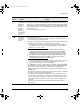
When you “hot swap” modules in the switch slot, if you install a different module type
than the one that was previously installed in the slot, you must reset the switch so the
switch processor can properly initialize and configure the new module type. The flashing
LED informs you that this change of module types has occurred. The module will not work
properly until the switch is reset as indicated by all the module’s LEDs staying on until
the switch is reset.
See “Resetting the Switch” on page 17.
➌
The network
connection is
not working
properly.
Try the following procedures:
• For the indicated port, verify that both ends of the cabling, at the switch and the
connected device, are securely connected.
• Verify the connected device and switch are both powered on and operating correctly.
• Verify that you have used the correct cable type for the connection.
– for twisted-pair connections, in general, for connecting to an end node (MDI port),
use “straight- through” cable; for connecting to MDI-X ports on hubs or other
switches, use “crossover” cable.
Note: For the 100/1000Base-T Module in the default configuration (Auto), the
module automatically negotiates whether the port operates as MDI or MDI-X,
depending on the cable type and the connected device’s operation, and either
a straight-through or crossover cable can be used. If the module configuration
is changed to one of the fixed 100 Mbps options though (100-Half Duplex or 100-
Full Duplex), then the port operates as MDI-X only and the above statement
about straight-through and crossover cables applies.
– for fiber-optic connections, verify that the transmit port on the switch is connected
to the receive port on the connected device, and the switch receive port is
connected to the transmit port on the connected device.
• For a 1000 Mbps connection, verify that the network cabling complies with the IEEE
802.3ab standard. The cable should be installed according to the ANSI/TIA/EIA-568-
A-5 specifications. Cable testing should comply with the stated limitations for
Attenuation, Near-End Crosstalk, Far-End Crosstalk, Equal-Level Far-End Crosstalk,
and Return Loss.
The cable verification must include all patch cables from any end devices, including
the switch, to any patch panels in the cabling path.
• Verify that the port has not been disabled through a switch configuration change.
You can use the console interface, or, if you have configured an IP address on the
switch, use the web browser interface, or HP TopTools for Hubs & Switches network
management software to determine the state of the port and re-enable the port if
necessary.
• If the other procedures don’t resolve the problem, try using a different port or a
different cable.
Tip
Number
Problem Solution
2347.book Page 19 Tuesday, May 9, 2000 12:53 PM