
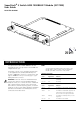
SuperStack 3 Switch 4400 1000BASE-T Module User Guide(English)

Activating the Module
1
Ensure that the Switch is powered-up.
2
Plug the RJ-45 connector on the Category 5 cable into
the RJ-45 socket on the Module.
3
Connect the other end of the Category 5 cable to a
device that supports 1000BASE-T.
4
Check the LEDs on the front of the Switch to ensure that
the Module is operating correctly. Refer to “
LEDs” for
more information.
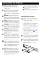
Removing the Module from a Switch
1
Ensure that the power supply and the backbone
connection cables are disconnected from the Switch.
2
Undo the Module’s two captive screws with a suitable
screwdriver. Do not remove any other screws from the
Switch.
3
Remove the Module.
4
If you are not fitting another Module immediately, you
must replace the blanking plate to ensure that dust and
debris do not enter the Switch. Replacing the blanking
plate will also help circulate cool air through the Switch.
When the Module is installed, you can configure it
through your Switch to add extra functionality. Refer to
the documentation that accompanies your Switch 4400
for more information.
When using the Module port, note the following:
The Module only operates at 1000 Mbps.
The Module only operates when it is connected to
another device that supports 1000BASE-T.
The Module only operates in full duplex mode.
The Module is not hot-swappable.
The Module is not hot-insertable.
The Module only operates with Category 5 Ethernet
cable.
.
If you suspect a problem, carry out these steps before
contacting your supplier:
Ensure that the Module is correctly installed in the
Switch.
Ensure that the Switch in which the Module is fitted is
powered-up.
Ensure that the device at the far end of the link is
powered-up and operating correctly.
Check that all connectors on the Category 5 cable are
correctly engaged.
For information about technical support, refer to the
documentation supplied with your Switch.
I
NSTALLATION
AND
R
EMOVAL
M
ANAGING
THE
M
ODULE
M
ODULE
P
ORT
R
ESTRICTIONS
P
ROBLEM
S
OLVING
3