Installation Guide ProCurve Switch cl Modules www.hp.
ProCurve Switch cl Modules Installation Guide
© Copyright 2005, 2006, 2012 Hewlett-Packard Development Company, L.P. The information contained herein is subject to change without notice. This document contains proprietary information, which is protected by copyright. No part of this document may be photocopied, reproduced, or translated into another language without the prior written consent of HewlettPackard.
Contents ProCurve Switch cl Modules Installation Guide Descriptions . . . . . . . . . . . . . . . . . . . . . . . . . . . . . . . . . . . . . . . . . . . . . . . . . . . . 1-1 Features . . . . . . . . . . . . . . . . . . . . . . . . . . . . . . . . . . . . . . . . . . . . . . . . . . . . . . . . 1-2 Installing the Modules . . . . . . . . . . . . . . . . . . . . . . . . . . . . . . . . . . . . . . . . . . . . 1-5 Installing a Module . . . . . . . . . . . . . . . . . . . . . . . . . . . . . . . . . . . . . .
EMC Regulatory Statements . . . . . . . . . . . . . . . . . . . . . . . . . . . . . . . . . . . . . . 1-23 U.S.A. . . . . . . . . . . . . . . . . . . . . . . . . . . . . . . . . . . . . . . . . . . . . . . . . . . . . 1-23 Canada . . . . . . . . . . . . . . . . . . . . . . . . . . . . . . . . . . . . . . . . . . . . . . . . . . . . 1-23 Australia/New Zealand . . . . . . . . . . . . . . . . . . . . . . . . . . . . . . . . . . . . . . . 1-23 Japan . . . . . . . . . . . . . . . . . . . . . . . . . . . . . . .
Descriptions ProCurve Switch cl Modules Descriptions The ProCurve Switch cl Modules are components you can add to a ProCurve cl switch to provide a variety of network connectivity options. The following modules are available as of this printing: Module Description ProCurve Switch CX4 cl Module (J8434A) 2-port 10 Gigabits CX4 transceiver switch expansion module. ProCurve Switch Media Flex cl Module (J8435A)1 2-port 10 Gigabits Media Flex switch expansion module.
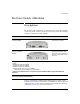
Features Features Module Power and Fault LEDs Link and Activity LEDs (one pair per port) ProCurve Switch Copper cl Module Extractor Handles Copper Port connections Retaining screw ProCurve Switch Media Flex cl Module Extractor Handles Module Power and Fault LEDs Link and Activity LEDs (one pair per port) 2 Port covers Retaining screw
Features The ProCurve Switch cl Modules have the following features: ■ Connectivity to both copper and fiber when using a Media Flex cl module. ■ LEDs that provide information for each port on the link status, network activity. ■ LEDs that provide information on Module power and Module fault conditions.
— This page is intentionally unused.
Installing the Modules Installing the Modules You can install any of the modules into any of the ProCurve cl Switches that have a compatible module slot. As of this printing, those are the ProCurve Series 3400cl Switch: ■ 3400cl-24G (J4905A) ■ 3400cl-48G (J4906A) ProCurve Series 6400cl Switch: 6400cl-6XG CX4 (J8433A) ■ 6410cl-6XG X2 (J8474A) ■ “Hot Swap” Notes The transceivers can be “hot swapped”.
Installing the Modules Installing a Module Installation Precautions: ■ Static electricity can severely damage the electronic components on the modules. When handling and installing the modules in your switch, follow these procedures to avoid damage from static electricity: • Handle the module by its bulkhead or edges and avoid touching the components and the circuitry on the board.
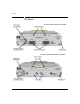
Installing the Modules 1. Remove the cover plate. Retaining screws 2. Insert module into the guides and slide it in until the extractors come in contact with the chassis. For best results, push simultaneously near both screws. Extractors 3. Push the extractor handles closed and tighten the retaining screws.
Installing the Modules Installing or Removing the transceivers If you installed a copper module you can now connect the cables. If you installed a media flex module, you can now install the transceivers. You can install or remove a transceiver from the Media Flex cl Module without having to power off the switch. Use only ProCurve transceivers. Installing the transceivers: WARNING The ProCurve X2 fiber optic transceivers are Class 1 or Class 1M laser devices.
Installing the Modules Verifying the Module is Installed Correctly Observe the Module Status and Fault LEDs on the front of the switch to verify the module is installed properly. Module Status LED Fault LED Module Status LED Fault LED When the module is installed properly and the switch is powered on, or the module is installed when the switch already has power, the module undergoes a self test that takes a few seconds.
Installing the Modules Connecting the Network Cables Supported Cable Types Table 1. Fiber-Optic Cables Port Type Cable Specifications Connector Type 10-GbE SR Multimode fiber-optic cable designed for Gigabit Ethernet: 62.5/125 µm (core/cladding) diameter or 50/125 µm, low metal content, complying with the ITU-T G.652 and ISO/IEC 793-2 Type B1 standards. 1 SC 10-GbE LR 9/125 µm (core/cladding) diameter, low metal content, single mode fiber-optic cables, complying with the ITU-T G.
Installing the Modules Connecting Cables Connecting the Fiber cable 1. Remove the dust covers from the cable connectors on the transceiver port. 2. Aligning the notches on the cable connectors with the slots of the transceiver ports, press the cable connector into the transceiver port until it snaps into place. 1 2 Note To ensure proper transmit/receive connections, make sure the transmit from one device is connected to the receive of the other device. Connecting the Copper cable 1.
Installing the Modules Verifying the Network Connections Are Working Check the port LEDs for the newly-installed module to ensure the port(s) connected in the preceding step are operating correctly. Each port on the switch modules has Link and Activity LEDs near it as shown in the next illustration. ■ On the 48 port 3400cl switch, Port A is port 49 and Port B is port 50.
Removing a Module Removing a Module Note Installing or removing a module with the switch powered on causes a switch reset to occur. Follow these procedures to remove a module: 1. Remove any network cables from the ports on the module. 2. On the module unscrew the retaining screws enough to disconnect them from the threaded holes in the switch. unscrew the retaining screws Pull extractor handles Caution 3. Using the extractor handles, pull the module out from the slot. 4.
Resetting the Switch Resetting the Switch Reasons for Resetting the Switch Generally, you only need to reset the switch when it needs to recognize a change in its hardware or software (console) configuration.
Troubleshooting Troubleshooting One of the primary tools for troubleshooting the switch modules are the LEDs on the front of the switch and on the modules. Refer to “LED Behavior” on page 9 for a description of the normal LED behavior. Also, refer to the switch Installation and Getting Started Guide for more detailed troubleshooting information for the switch.
Troubleshooting Tip Number Problem Solution ➊ The network port for which the Link LED is blinking has experienced a self test or initialization failure. During the module self test (described in item 1 above), each network port is also tested. If the port self test fails, the individual port is not usable, but the rest of the ports on the module, which have passed their self test, will continue to operate normally.
Customer Support Services Customer Support Services If you are having any trouble with your module or switch, ProCurve offers support 24 hours a day, seven days a week through the use of a number of automated electronic services. See the Customer Support/Warranty booklet that came with your switch for information on how to use these services to get technical support. The ProCurve networking products Web site, http://www.procurve.com also provides up-to-date support information.
Specifications Specifications Physical MODULES Width: 114.3 mm (4.5 in) Depth: 173 mm (6.8125 in) Height: 40.8 mm (1.6 in) Weight: CX4 J8434A 308.5g (0.68 lbs) Media Flex J8435A 297.6g (0.65 lbs) TRANSCEIVERS 18 SR Optic J8436A LR Optic J8437A ER Optic J8438A Copper J8440A Width: 36 mm (1.42 in) 36 mm (1.42 in) Depth: 88.6 mm (3.48 in) 89.8 mm (3.54 in) Height: 11 mm (.43 in) 18.96 mm (.
Specifications Environmental MODULES Operating Non-Operating Temperature: 0°C to 55°C (32°F to 131°F) -40°C to 70°C (-40°F to 158°F) Relative humidity: (non-condensing) 15% to 95% at 40°C (104°F) 15% to 90% at 65°C (149°F) Maximum altitude: 4.6 km (15,000 ft.) 4.6 km (15,000 ft.
Optical Power Specifications Optical Power Specifications ProCurve 10-GbE X2-SC SR optic (J8436A) Transmitter Optical Characteristics: Parameter Minimum Average Launch Power -7.3dBm Extinction Ratio 3dB Typical Notes -1.0dBm RIN (Relative Intensity Noise) Nominal Wavelength Maximum -128dB/Hz 840nm 850nm 860nm Receiver Optical Characteristics: Parameter Minimum Typical Maximum Center Wavelength 840nm 850nm 860nm Saturation Receiver Power -1.0dBm Receiver Sensitivity -11.
Optical Power Specifications ProCurve 10-GbE X2-SC LR optic (J8437A) Transmitter Optical Characteristics: Parameter Minimum Average Launch Power -8.2dBm Extinction Ratio 3.5dB Typical Notes 0.5dBm 8dB RIN (Relative Intensity Noise) Nominal Wavelength Maximum -128dB/Hz 1260nm 1310nm Spectral Width 1355nm 0.2nm Receiver Optical Characteristics: Parameter Minimum Typical Receiver Sensitivity Center Wavelength Notes -12.
Optical Power Specifications ProCurve 10-GbE X2-SC ER optic (J8438A) Transmitter Optical Characteristics: Parameter Minimum Average Launch Power -4.7dBm Nominal Wavelength 1530nm Extinction Ratio Typical Maximum Notes 4.0dBm 1550nm 1565nm 3dB RIN (Relative Intensity Noise) -128dB/Hz with 21dB return loss Maximum Notes Receiver Optical Characteristics: Parameter Minimum Typical Receiver Sensitivity Center Wavelength -14.
EMC Regulatory Statements EMC Regulatory Statements U.S.A. FCC Class A This equipment has been tested and found to comply with the limits for a Class A digital device, pursuant to Part 15 of the FCC Rules. These limits are designed to provide reasonable protection against interference when the equipment is operated in a commercial environment.
European Community Declaration of Conformity Korea Taiwan 24
Recycle Statements Recycle Statements Waste Electrical and Electronic Equipment (WEEE) Statements Disposal of Waste Equipment by Users in Private Household in the European Union This symbol on the product or on its packaging indicates that this product must not be disposed of with your other household waste. Instead, it is your responsibility to dispose of your waste equipment by handing it over to a designated collection point for the recycling of waste electrical and electronic equipment.
Recycle Statements Laitteiden hävittäminen kotitalouksissa Euroopan unionin alueella Jos tuotteessa tai sen pakkauksessa on tämä merkki, tuotetta ei saa hävittää kotitalousjätteiden mukana. Tällöin hävitettävä laite on toimitettava sähkölaitteiden ja elektronisten laitteiden kierrätyspisteeseen. Hävitettävien laitteiden erillinen käsittely ja kierrätys auttavat säästämään luonnonvaroja ja varmistamaan, että laite kierrätetään tavalla, joka estää terveyshaitat ja suojelee luontoa.
Recycle Statements Smaltimento delle apparecchiature da parte di privati nel territorio dell'Unione Europea Questo simbolo presente sul prodotto o sulla sua confezione indica che il prodotto non può essere smaltito insieme ai rifiuti domestici. È responsabilità dell'utente smaltire le apparecchiature consegnandole presso un punto di raccolta designato al riciclo e allo smaltimento di apparecchiature elettriche ed elettroniche.
Recycle Statements Descarte de Lixo Elétrico na Comunidade Européia Este símbolo encontrado no produto ou na embalagem indica que o produto não deve ser descartado no lixo doméstico comum. É responsabilidade do cliente descartar o material usado (lixo elétrico), encaminhando-o para um ponto de coleta para reciclagem.
Technical information in this document is subject to change without notice. Copyright Hewlett-Packard Development Company, 2005-2006, 2012. All rights reserved. Reproduction, adaptation, or translation without prior written permission is prohibited except as allowed under the copyright laws.