3Com® 5500G Open Services Networking Module Getting Started Guide www.3Com.
3Com Corporation 350 Campus Drive Marlborough, MA 01752-3064 Copyright © 2007-2008, 3Com Corporation. All rights reserved. No part of this documentation may be reproduced in any form or by any means or used to make any derivative work (such as translation, transformation, or adaptation) without written permission from 3Com Corporation.
Contents Introduction Get the latest documentation and software for your 3Com OSN|M About this guide 5 1 OSN|M Overview 2 OSN|M Hardware Overview Appearance 9 Front Panel 9 Hardware Configuration 3 12 OSN|M Installation Installing and Removing the OSN|M 15 Connecting the Management Ethernet Port Cable 4 5 17 Logging Into the OSN|M Linux System Login Options 19 Logging In Through the Console Port 19 Logging In Through the OSN|M Management Ethernet Port Using SSH 20 Logging In Through the OSN|M In
Get the latest documentation and software for your 3Com OSN|M 5 Introduction Get the latest documentation and software for your 3Com OSN|M Thank you for purchasing the 3Com® OSN|M Open Services Networking Module. As part of our commitment to help you get the most out of your 3Com network equipment, we offer updated documentation and software on our web site. To obtain the most up-to-date user documentation and operating software for the 3Com OSN|M, point your web browser to: www.3Com.
Introduction
1 OSN|M Overview You can use the Open Services Networking Module (OSN|M) as an expansion module installed in an expansion module slot on the rear panel of a Switch 5500G. It provides a software and hardware platform that can run various services. After an OSN|M is inserted into the expansion module slot, it interacts with the switch through its two internal service interfaces, which conforms to the software and hardware interface specifications defined by OSN. An OSN|M runs an independent Linux system.
Chapter 1: OSN|M Overview
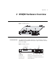
Appearance 9 2 OSN|M Hardware Overview Appearance Figure 1 displays the front view of the OSN|M. Figure 1 OSN|M appearance Front Panel Front Panel View This section describes the OSN|M’s front panel. An OSN|M provides one USB 2.0 interface, one console port, and one 10/100 Base-TX management Ethernet port. Figure 2 illustrates the front panel of an OSN|M.
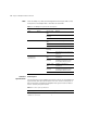
Chapter 2: OSN|M Hardware Overview LEDs There are PWR, SYS, HDD, and management Ethernet port LEDs on the front panel of an OSN|M. Table 1 describes the four LEDs. Table 1 The OSN|M front panel’s LED descriptions LED Color Status Function PWR Green Green, solid ON Normal Green, blinking The module is being loaded. OFF The module is powered off. Green, solid ON CPU bus is busy Red, solid ON CPU bus fails.
Front Panel 11 Table 2 Console port specifications Specification Description Interface standard EIA/TIA-232 Cable type Asynchronous serial port cables Baud rate (bps) ■ 300 ■ 1200 ■ 2400 ■ 4800 ■ 9600 (default) ■ 19200 ■ 38400 ■ 56000 ■ 115200 Management Ethernet port You can use the 10/100Base-TX management Ethernet port on the OSN|M’s front panel for management only; not for exchanging data.
Chapter 2: OSN|M Hardware Overview USB interface Use the USB interface on the OSN|M’s front panel to connect a storage medium such as a USB flash disk to perform file related operations. Refer to Table 4 for the USB interface specifications. Table 4 USB interface specifications Specification Description Connector type USB interface Number of connectors 1 Interface standard USB 2.0 (backward compatible) Transmit rate ■ low-speed mode: 1.
Hardware Configuration 13 Table 6 Default partitioning of the OSN|M hard disk Partition name Mount point Format of file system /dev/hda2 /alt ext3 The root file system’s backup partition. Its leave-factory setting is null. /dev/hda3 swap swap The Linux system’s swapping partition. When you boot from hard disk using Elilo, it uses this partition as the system’s swapping partition. /dev/hda5 /opt ext The partition provided for the users. It is the system’s largest partition.
Chapter 2: OSN|M Hardware Overview
Installing and Removing the OSN|M 15 3 OSN|M Installation Installing and Removing the OSN|M The Switch 5500G supports hot swapping the OSN|M. c CAUTION: If the Linux system is running on an OSN|M, use the poweroff command to exit the system before removing the OSN|M. Installing an OSN|M in a Switch 5500G To install the OSN|M, perform the following steps: 1 Put on an ESD-preventive wrist strap and make sure that the ESD-preventive wrist strap is properly grounded.
Chapter 3: OSN|M Installation Figure 3 Install an OSN|M in a switch (1) (2) (1) Rear panel of the switch (2) Front panel of the OSN|M Removing the OSN|M 1 Put on an ESD-preventive wrist strap and ensure that the ESD-preventive wrist strap is properly grounded. 2 Loosen the fastening screws on both sides of the OSN|M using a screwdriver. 3 Hold the two sides of the OSN|M front panel with both hands and draw back the module until the module is fully separated from the switch.
Connecting the Management Ethernet Port Cable 17 Connecting the Management Ethernet Port Cable c 1 2 To connect the management Ethernet port cable, perform the following steps: CAUTION: When connecting the cable, pay attention to the mark on the interface to insert it in the correct direction, otherwise, you may damage the interface or the OSN|M. Connect the management Ethernet port to a terminal.
Chapter 3: OSN|M Installation
Login Options 19 4 Logging Into the OSN|M Linux System Login Options You can log into the OSN|M Linux system through: ■ The OSN|M’s console port. ■ The OSN|M’s management Ethernet port using SSH. ■ The OSN|M’s internal service interface using SSH ■ A serial port redirection after you log into the switch. You can connect to the switch’s OSN|M or to another switch’s (within the same fabric) OSN|M to which you have logged in through a CLI.
Chapter 4: Logging Into the OSN|M Linux System Logging In Through the OSN|M Management Ethernet Port Using SSH The SSH server function is enabled on the OSN|M by default. You can use SSH on the SSH client to log into the Linux system through the OSN|M’s management Ethernet port performing the following steps: 1 Connect one end of the cable to the switch’s Ethernet port and the other end to the OSN|M’s management Ethernet port.
Logging In Through the OSN|M Internal Service Interface Using SSH 21 Logging In Through the OSN|M Internal Service Interface Using SSH After you install the OSN|M into the Switch 5500G’s expansion module slot, the OSN|M exchanges information with the switch through its two internal service interfaces, which display as Eth0 and Eth1 in the Linux system. The Switch 5500G provides two internal ports GigabitEthernet 1/1/1 and GigabitEthernet 1/1/2 to connect with Eth0 and Eth1.
Chapter 4: Logging Into the OSN|M Linux System Configuration procedure 1 Ensure network connectivity between the SSH client and the OSN|M’s Eth1 interface. 2 Configure the SSH client’s IP address and that of the Eth1 interface to be on the same network segment. The IP address of Eth1 is 10.10.10.6/24 by default. 3 Add the following two switch ports to the same VLAN: ■ The port connected with SSH client, GigabitEthernet 1/0/2 in this example.
Logging In through a Switch 5500G Command Line Interface 23 osm connect unit 1 Connected to OSM ! Fedora Core release 6 (Zod) Kernel 2.6.18.8 on an i686 localhost.localdomain login: # Enter the username and password. The default username and password are both root. localhost.localdomain login: root Password: Last login: Sun Jan 2 12:52:22 on ttyS1 [root@localhost ~]# You have logged into the Linux system and can now configure and manage the system.
Chapter 4: Logging Into the OSN|M Linux System
BIOS Menu 25 5 Understanding and Using the BIOS Options BIOS Menu Entering the BIOS Menu When the OSN|M is powered on, the following information is displayed: ************************************************* * * * BIOS , Ver 1.17 * * * ************************************************* Copyright(c) 2005-2007 by 3Com Corporation.
Chapter 5: Understanding and Using the BIOS Options Shutting down smartd: [ OK ] Stopping yum-updatesd: [FAILED] Stopping atd: [ OK ] Stopping cups: [ OK ] Shutting down console mouse services: [ OK ] Stopping sshd: [ OK ] Shutting down sm-client: [ OK ] Shutting down sendmail: [ OK ] Stopping acseic-daemon: [ OK ] Stopping acpi daemon: [ OK ] Stopping crond: [ OK ] Shutting down RPC idmapd: [ OK ] Stopping autofs: Stopping automount: [ OK ] [ OK ] Stopping system message bus: [ OK ] Stopping NFS statd:
Booting the Linux System 27 BIOS Menu Options Press Ctrl+D when Press Ctrl-D to enter BIOS Menu... appears, and the system displays the BIOS menu. <1> Boot Linux From HardDisk <2> Boot Linux From USB <3> Install Linux OS With Ethernet <4> Enter Internal Shell <5> Reboot Enter your choice(1-5): Table 7 describes the menu options. Table 7 BIOS menu Menu item Description <1> Boot Linux From HardDisk Read the boot program from hard disk and then boot the Linux system.
Chapter 5: Understanding and Using the BIOS Options Booting the Linux System from the USB Storage Medium If you enter 2 in the BIOS menu, the BIOS reads the boot program from the storage medium connected to the USB interface to boot the Linux system. This function provides a shortcut to rapid system restoration. You can backup part of the system installation files into an external storage medium, such as a USB flash disk.
Installing the Linux System through an Ethernet Connection 29 Figure 5 Network diagram for an Ethernet installation through Eth1 Internal connection between the OSN|M and the switch Eth1 TFTP Server GE 1/1 /2 Switch with OAP IP network GE 1/0 /2 on switch Console on OSN|M Controller DHCP Server Figure 6 Network diagram for Ethernet installation through the management Ethernet port Eth2 TFTP Server Switch with OSN|M IP network Management Ethernet port (Eth2) on OSN|M Console on OSN|M Controller
Chapter 5: Understanding and Using the BIOS Options available with the software releases.) Create a directory named 3CR17280-72 on the server, and put the configuration file in this directory. Table 8 The Linux system installation files File name 3 Description Initrd The ramdisk file generated by busybox. bzImage The kernel file generated by busybox. elilo.efi Linux boot loader elilo.conf ELILO configuration file disk.tar.gz Mirror image file of the hard disk Vfat.tar.
Installing the Linux System through an Ethernet Connection 31 address and IP address. For example, when obtaining the configuration file from the TFTP server, the OSN|M module with the IP address 10.10.10.
Chapter 5: Understanding and Using the BIOS Options c If neither Next server IP address nor TFTP Server Name (Option 66) is configured for the DHCP server, the OAP module considers that the DHCP server can also serve as the TFTP server, and takes the IP address of the DHCP server as the IP address of the TFTP server. 3 The following example shows the DHCP server’s configuration file’s content.
Installing the Linux System through an Ethernet Connection 33 / # pxe_install Try to do network install on eth1..... Get the ip address from dhcp-server..... udhcpc (v1.6.0) started Sending discover... Sending select for 10.10.10.91... Lease of 10.10.10.91 obtained, lease time 21600 Get TFTP server IP address from DHCP by NextServer The TFTP server IP address is: 10.10.10.10 Get config file setup/3CR17280-72/01-00-00-12-34-56-7 9.....Fail Get config file setup/3CR17280-72/0A0A0A5B.....
Chapter 5: Understanding and Using the BIOS Options n Entering the Internal Shell Command Line After the kernel file and ramdisk file are loaded, the system prompts / #. In this case, you can use the fdisk command to view the Linux file system and to perform file operations or manually update system files. System restoration or upgrades in this way does not result in reformatting the hard disk. Enter 4 in the BIOS menu to enter the Internal Shell command line.
Upgrading the BIOS 35 TFTP-server-IP-address: IP address of the TFTP server selected. btm-file-name: Name of the installation file (a .btm file). The TFTP server and the selected ONS|M interface must be on the same network segment. Upgrading the BIOS Through Interface Eth1 Network diagram Install the ONS|M module in a Switch 5500G. You can log in to the Linux system of the ONS|M module to enter the Internal Shell command line and upgrade the BIOS using one of several methods.
Chapter 5: Understanding and Using the BIOS Options After completing the BIOS upgrade, you can use the reset command to exit the Internal Shell command line and restart the BIOS. Upgrading BIOS Through Eth2 Network diagram Install the OAP module in an S5600 switch. Controller can log in to the Linux system of the OAP module to enter the Internal Shell command line to upgrade the BIOS in many ways. The following exemplifies the network diagram and installation process of BIOS upgrade.