
3Com® Switch 5500G Open Services Networking Configuration and Command reference Guide


ACFP Configuration Example 17
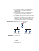
■ The IP address of Host A is 192.168.1.1/24, and that of Host B is
192.168.2.1/24. They are connected to the switch through
GigabitEthernet 1/0/1.
■ The IP address of Host C is 192.168.3.1/24, and that of Host D is
192.168.3.2/24. They are connected to the switch through
GigabitEthernet 1/0/2.
■ The OSN|M (ACFP client) is installed in the expansion module slot on
the switch’s rear panel. The ACFP client is used to analyze traffic on
ACFP server’s GigabitEthernet 1/0/1 port. After the ACFP client
analyzes the traffic, all packets with the source IP address in network
segment 192.168.1.0/24 are permitted and all packets with the
source IP address in network segment 192.168.2.0/24 are denied.
Network Diagram
Figure 3 Network diagram for an ACFP configuration
Configuration
Procedure
■ Configure the Switch.
# Enable ACFP.
<Switch> system-view
[Switch] acfp enable
■ Configure the collaboration policy and rules for the ACFP client
through MIB.
# Configure the ACFP client.
192.168.1.1/24
Host A
192.168.2.1/24
Host B
GE1/1/1
GE1/0/2
Switch
ACFP client
192.168.3.1 /24
Host C
192.168.3.2 /24
Host D
ACFP server
GE1/0/1