
Advanced Services v2 zl Module Quickstart Guide

HP Advanced Services v2 zl Module Quickstart 2 Important information to read before installing
Important information to read before installing
Safety: Static electricity can severely damage the electronic components on
the module. When handling and installing the module, follow these procedures
to avoid damage from static electricity:
•
Handle the module by its bulkhead or edges, and avoid touching the
components and the circuitry on the board.
•
When installing the module, equalize any static charge difference between
your body and the switch by wearing a grounding wrist strap and attaching
it to the metal body of the switch, or by frequently touching the metal body
of the switch.
•
For safe operation, proper switch cooling, and reduction of
electromagnetic emissions, ensure that a slot cover is installed on any
unused module slot. For safety, no more than one slot must be uncovered
at a time when the switch is powered on.
Environmental and regulatory information
Installation
Inserting the module into a switch chassis
1. Use a Torx T-10 or flat-blade screwdriver to loosen the screws in the slot
cover where the module is to be installed. Remove the slot cover and
store for possible future use.
2. Hold the module by its bulkhead, taking care not to touch the connectors
or components on the boards.
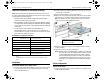
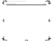
3. Open the extractor handles (1 in the following figure).
4. Aligning the lower PC board with the guides in the slot, insert the module
and slide it into the slot until it is fully inserted (2 in the following figure).
Note: The switch has low force, high-performance connectors. Avoid
using excessive force when installing the module.
5. When the contacts have engaged, use the extractor handles to seat the
module completely.
6. Tighten the screws on each side of the module.
Note:
When the module is installed properly, it undergoes a self-test that
takes 30 to 45 seconds. This happens when the switch is powered
on after installing the module and when the module is installed
while the switch already has power. The LEDs on the switch and
module indicate if the module has passed the self-test. For more
information, see the Advanced Services v2 zl Module Installation
Guide.
Initial configuration
Connect to the switch
1. Using a serial console cable, connect a computer to the serial port of the
switch Management Module.
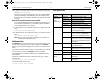
Environmental
Operating Temperature
0°C to 45°C (32°F to 113°F)
Relative humidity
15% to 95% at 40°C (104°F)
a
(non-condensing)
a. The HDD (J9857A) has a maximum operational wet bulb temperature of 28°C
(82°F).
Non-operating temperature -40°C to 70°C (-40°F to 158°F)
Non-operating relative humidity
15% to 90% at 65°C (149°F)
b
(non-condensing)
b. The HDD(J9857A) has a maximum non-operational wet bulb temperature of 28°C
(82°F).
Operating maximum altitude 3.0 km (10,000 ft)
Non-operating maximum altitude 4.6 km (15,000 ft)
Safety standards
UL 60950-1; IEC 60950-1; EN 60950-1;
CAN/CSA-C22.2 No. 60950-1
EMC: Class A standards
EN 55022; EN 55024; EN 61000-3-2 +A1, +A2; EN
61000-3-3; FCC CFR 47 Part 15
Advanced Services v2 zl installation
1: Extractor handles in open position
2: Module being inserted
5998-4959_QS_Advanced_Services_v2_zl_Controller.fm Page 2 Wednesday, December 4, 2013 4:26 PM