HP AllianceONE Services zl Module for Avaya Aura Session Border Controller powered by Acme Packet Installation and Getting Started Guide
HP AllianceONE Services zl Module for Avaya Aura Session Border Controller powered by Acme Packet September, 2010 Installation and Getting Started Guide
© Copyright 2010 Hewlett-Packard Development Company, L.P. The information contained herein is subject to change without notice. All Rights Reserved. This document contains proprietary information, which is protected by copyright. No part of this document may be photocopied, reproduced, or translated into another language without the prior written consent of HewlettPackard.
Contents 1 Overview Providing SIP Trunk Connectivity . . . . . . . . . . . . . . . . . . . . . . . . . . . . . . . . . 1-1 Switch-Based Deployment . . . . . . . . . . . . . . . . . . . . . . . . . . . . . . . . . . . . . 1-2 Licensing . . . . . . . . . . . . . . . . . . . . . . . . . . . . . . . . . . . . . . . . . . . . . . . . . . . 1-3 2 Hardware Installation Hardware Overview . . . . . . . . . . . . . . . . . . . . . . . . . . . . . . . . . . . . . . . . . . . 2-1 Operating Systems . . . . . . . . . .
Pre-configured System Platform Management IP Addresses . . . . . . . . . . . 3-5 Configuring System Platform Management IP and MAC Addresses . . . . . 3-6 Notes on Installing the SBC Template . . . . . . . . . . . . . . . . . . . . . . . . . . . . . . 3-7 Next Steps . . . . . . . . . . . . . . . . . . . . . . . . . . . . . . . . . . . . . . . . . . . . . . . . . . . . . 3-8 A EMC Regulatory Statements U.S.A. - FCC Class A . . . . . . . . . . . . . . . . . . . . . . . . . . . . . . . . . . . . . . . .
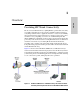
1 Overview Overview Providing SIP Trunk Connectivity The use of Session Initiation Protocol (SIP) Trunks to provide SIP connectivity is a rapidly expanding part of the network capabilities in many businesses today. The potential to reduce equipment and service costs, increase flexibility in network expansion, and provide both voice and data over the same connection makes a very compelling case for the use of SIP Trunking.
Overview Providing SIP Trunk Connectivity The product’s supported features include: ■ Multiprotocol signaling (SIP, H.323, and SIP/H.
Overview Providing SIP Trunk Connectivity • Avaya Aura™ SBC Objects and Properties Reference • Avaya Aura™ SBC Session Services Configuration Guide • Avaya Aura™ SBC System Administration Guide • Avaya Aura™ SBC System Operations and Troubleshooting Guide These documents are available from Avaya at http://www.avaya.com/support. Licensing The Avaya Aura™ Session Border Controller Application must be installed and running on the System Platform before you can request a license.
(This page intentionally left blank.
2 The HP AllianceONE Services zl Module for Avaya Aura™ Session Border Controller powered by Acme Packet is designed to run in an HP 5400zl or 8200zl Series switch. Table 2-1 lists the tasks that you perform to get the HP Extended Services zl Module up and running so that you can begin the initial configuration process (as outlined in Chapter 3: “Getting Started”). If the HP zl switch has already been installed, move to “Update the Switch Software” on page 2-3. Table 2-1.
Hardware Installation Module Shutdown button Module HDD and Network Management PCIe slots (not used) Module Status LED USB port Figure 2-1. Front panel Operating Systems When the HP Extended Services zl Module ships, it includes a Hard Disk Drive (HDD), a Compact Flash (CF), and the module itself, along with: ■ HP Service OS The primary and backup Service OS reside on the Compact Flash (CF).
Hardware Installation Update the Switch Software Figure 2-2. The Avaya Aura™System Platform Is Stored on an HDD, Located on the Top of the Module. Note The printed version of this document, shipped with the product, contains the basic information needed to get you started using the module. It also contains EMC Regulatory Statements (Appendix A) and Waste Electrical and Electronic Equipment (WEEE) Statements (Appendix B). Appendices C and D are only in the Web version of this document at http://www.hp.
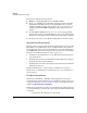
Hardware Installation Update the Switch Software Before installing the HP Extended Services zl Module, you must update the HP zl switch software to version K.14.60 or greater. Otherwise, the switch will not recognize the module. Follow these steps to install the new software: 1. Using a management workstation that has Internet connectivity, access the HP Web site and download the K.14.60 switch software from the HP Networking Web site (www.hp.com/networking/software). 2.
Hardware Installation Update the Switch Software Note If you need to cancel this command, press either [Ctrl-C] or [Ctrl-Z]. Both cancel the command, but [Ctrl-Z], unlike [Ctrl-C], does not provide any message indicating that the command was cancelled. 5. After the file has finished copying, you should see the prompt again as shown in Figure 2-3. Figure 2-3. HP zl Switch CLI—Software Copied 6.
Hardware Installation Set the HP zl Switch Time You should see the following output. hostswitch: show version Management Module 1: Active Image stamp: /sw/code/build/btm(t4a) Apr 22 2010 20:05:26 K.14.60 69 Boot Image: Secondary hostswitch# Set the HP zl Switch Time To follow best practices, you should ensure that the HP zl switch is using the correct time.
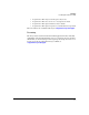
Hardware Installation Set the HP zl Switch Time 4. Configure the SNTP server IP address (either the domain controller or an SNTP server with the correct time): Syntax: sntp server priority 1 Replace with the reachable IP address of the domain controller or SNTP server. 5. Set the timezone: Syntax: time timezone <-780 - 840> The switch calculates the time zone offset in minutes. For example, to specify GMT +1, type 60. 6.
Hardware Installation Set the Time on the System Platform 2. Set the date: Syntax: clock set
- Replace
- with the two-digit date, two-digit month number, and four-digit year. For example, 05/24/2010 3. Set the time (which must be within a few minutes of the domain controller’s time): Syntax: clock set Replace with the two-digit hour in the 24-hour clock, two-digit minute, and two digit seconds. For example, 10:09:35. 4.
Hardware Installation Install the HP Extended Services zl Module time across a network helps to ensure proper coordination and operation among all network components. Setting the time accurately also ensures that event logs use the correct time, allowing you to monitor or troubleshoot problems more easily. The Avaya Aura™ Session Border Controller Application initially gets the time from the System Platform Local Clock, which receives the current time from the HP zl switch.
Hardware Installation Install the HP Extended Services zl Module Installation Precautions(Continued) ■ For safe operation, proper switch cooling, and reduction of electromagnetic emissions, ensure that a slot cover is installed on any unused module slot. For safety, no more than one slot should be uncovered at a time, even temporarily, when the switch is powered on. ■ Check the temperature specifications for the module; different modules have different temperature requirements.
Hardware Installation Install the HP Extended Services zl Module 6. Tighten the screws. Insert module into the guides and slide in until fully inserted. Open extractor handles. Figure 2-4. Module being installed The procedure to replace or remove a module is described on page C-7 in the Web version of this document at http://www.hp.com/networking/manuals. Appendix C also describes the procedure to replace the module’s Hard Disk Drive (HDD) and the Compact Flash (CF) card.
Hardware Installation Install the HP Extended Services zl Module After this first bootup process, the Extended Services zl Module always undergoes a self test when it reboots or powers on (this process takes closer to two or three minutes). Again, the LEDs help you to determine if the module has passed the self test, as described in the table below. Table 2-2.
Hardware Installation Environmental Specifications Environmental Specifications Table 2-3 lists the maximum temperatures and other environmental specifications for Extended Services zl Modules. Table 2-3. Environmental Specifications Temperature Operating Non-Operating 0°C to 45°C (32°F to 113°F)1 -10°C to 65°C (-10°F to 149°F) Relative humidity (non-condensing) 15% to 90% at 40°C (104°F) 15% to 90% at 65°C (149°F) Maximum altitude 3.0 km (10,000 ft) 4.6 km (15,000 ft) 1.
(This page intentionally left blank.
3 Getting Started Getting Started Initial Switch Configuration At this point, the HP Extended Services zl Module, with the pre-installed System Platform, should be installed in an HP 5400zl or 8200zl Series switch.
Getting Started Initial Switch Configuration You will see output similar to the following: Status and Counters – Module Information Chassis: 5406zl J8697A Management Module: J8726A Serial Number: SG841SU0RI Serial Number: ID839AS0F6 Slot Module Description Serial Number ---- --------------------------------------A >Module C Extension Slot C ProCurve J9567A ONE Ext Svs zl Module SG9604Q083 D ProCurve J9308A Gig-T/SFP PoE+ zl Module Notice that output shows the Extended Services zl Module (ProCurve J9567A
Getting Started Initial Switch Configuration Port 1 (1) is sometimes referred to as the outside or public port because traffic from the internal network is sent through this port to a public network. Port 2 (2) is sometimes referred to as the inside or private port because it functions as a normal traffic port in the private network. In addition, management traffic and communications between the Extended Services zl Module and the HP zl switch are sent on this port.
Getting Started Initial Switch Configuration hostswitch# config hostswitch(config)# vlan 1 hostswitch(vlan-1)# name "DEFAULT_VLAN" hostswitch(vlan-1)# ip address dhcp-bootp hostswitch(vlan-1)# no untagged c1-c2 hostswitch(vlan-1)# write memory hostswitch(vlan-1)# exit hostswitch(config)# interface c1 name "public-interface" hostswitch(config)# interface c2 name "private interface" ProCurve Switch 8212zl(config)# sho interfaces custom c1,c2 port name:25 Status and Counters - Custom Port Status Port Name ---
Getting Started Pre-configured System Platform Management IP Addresses hostswitch(vlan-200)# write memory No IP address is assigned, restricting traffic to only ports that are members of this VLAN. Configuring the Private Network Interface A switch VLAN is created containing the module port 2 as an untagged member. In the example below, VLAN 300, named Private, is created for use with the Extended Services zl Module in switch slot ‘c’.
Getting Started Pre-configured System Platform Management IP Addresses Interface Description Management port (Extended Services zl Module) Table 3-2. Default IP Address Out-of-band System Platform management using the CLI. Connect through this port using SSH from a laptop or terminal with IP address: 192.11.13.5. Only console devices should be connected to the Management port. To limit access, do NOT connect the Management port to a switch port. 192.11.13.
Getting Started Notes on Installing the SBC Template Border Controller CLI, in switch slot k, is accessed and the IP addresses are configured to their default values. This also replaces the default MAC addresses with unique ones. Important Dom-0 and cdom IP addresses must reside on the same subnet. Note When using the applications CLI (services k name Avaya-SBC), backspace by typing Control-Backspace or press the Delete key. These CLI commands also are case sensitive - ‘exit’ and ‘Exit’ are different.
Getting Started Next Steps 1. When using a USB CD/DVD drive, it must be powered by an external power supply. Check to see that the power supply is turned on before connecting the device to the module’s USB port. 2. If you choose to the load the template from either a USB drive or an externally powered USB CD/DVD drive, a USB hub cannot be used. Connect the USB device directly to the USB port on the front of the module. 3.
EMC Regulatory Statements A EMC Regulatory Statements U.S.A. - FCC Class A This equipment has been tested and found to comply with the limits for a Class A digital device, pursuant to Part 15 of the FCC Rules. These limits are designed to provide reasonable protection against interference when the equipment is used in a commercial environment.
EMC Regulatory Statements Japan - VCCI Class A Korea Taiwan European Community Declaration of Conformity This product is designed for operation with HP switches that have zl module slots. Refer to the Declarations of Conformity included in the Installation Guides for those products.
Waste Electrical and Electronic Equipment (WEEE) Statements B Waste Electrical and Electronic Equipment (WEEE) Statements Disposal of Waste Equipment by Users in Private Household in the European Union This symbol on the product or on its packaging indicates that this product must not be disposed of with your other household waste.
Waste Electrical and Electronic Equipment (WEEE) Statements Laitteiden hävittäminen kotitalouksissa Euroopan unionin alueella Jos tuotteessa tai sen pakkauksessa on tämä merkki, tuotetta ei saa hävittää kotitalousjätteiden mukana. Tällöin hävitettävä laite on toimitettava sähkölaitteiden ja elektronisten laitteiden kierrätyspisteeseen.
Waste Electrical and Electronic Equipment (WEEE) Statements Smaltimento delle apparecchiature da parte di privati nel territorio dell'Unione Europea Questo simbolo presente sul prodotto o sulla sua confezione indica che il prodotto non può essere smaltito insieme ai rifiuti domestici. È responsabilità dell'utente smaltire le apparecchiature consegnandole presso un punto di raccolta designato al riciclo e allo smaltimento di apparecchiature elettriche ed elettroniche.
Waste Electrical and Electronic Equipment (WEEE) Statements Descarte de Lixo Elétrico na Comunidade Européia Este símbolo encontrado no produto ou na embalagem indica que o produto não deve ser descartado no lixo doméstico comum. É responsabilidade do cliente descartar o material usado (lixo elétrico), encaminhando-o para um ponto de coleta para reciclagem.
Hardware Components Front Panel Buttons, LEDs, and Connectors C Hardware Components Front Panel Buttons, LEDs, and Connectors This section describes the different buttons, LEDs, and connectors on the front panel of a module: ■ Module Shutdown button—This button is used to shut down the module. A message is written to the switch log to indicate the module has shut down.
Hardware Components Front Panel Buttons, LEDs, and Connectors The following table describes the LEDs on the front panel. Table C-1. Module LEDs Module LED State Module Status1 (green/ orange) Meaning When the module is first installed, this LED follows the following sequence: 1. Green for ~15s - The module has power. 2. Orange for ~11s - Testing the LED. 3. Green for ~4s - Starting self-test. 4. Orange for ~30s - Self-test in progress. 5. Off - The module is booting the OS.
Hardware Components Upper Deck Upper Deck The module consists of an upper deck PCA, which supports a HDD, and provides PCIe slots. These slots are not used by the HP AllianceONE Services zl Module for Avaya Aura™ Session Border Controller. Internal Ports The module receives traffic from and transmits traffic to its host switch on two internal Ethernet ports, each of which supports 10 Gbps.
Hardware Components Serial Numbers Serial Numbers Serial numbers are required when contacting HP or a reseller for warranty assistance or for coverage under a service agreement. For future reference, record the serial and product numbers in the warranty booklet. The product ships as a bundle.
Hardware Components Serial Numbers The serial number for the module is located on the back left corner of the module (Figure C-2). Module serial number SN: SGxxxxxxxx Figure C-2.
Hardware Components Switch LEDs Switch LEDs The following figures show the Test, Fault, and Module Status LEDs on the switches the module can be installed in. Test LED Fault LED Module Status LEDs Figure C-4. Test, Fault, and Module Status LEDs on a Series 5400zl switch Fault LED Test LED Module Status LEDs Figure C-5.
Hardware Components Replacing or Removing a Module Replacing or Removing a Module It is highly recommended that the HP Extended Services zl Module be shutdown before replacing or removing it.
Hardware Components Field Replaceable Units (FRUs) Field Replaceable Units (FRUs) The module includes the following FRUs: ■ Disk Drive(s) ■ Compact Flash Please see the HP AllianceONE Extended Services zl Module Field Replaceable Unit (FRU) Installation Guide at www.hp.com/networking/support for installation instructions.
Software Components Updating Switch Software D Software Components Updating Switch Software The module requires switch software version K.14.60 or greater to be installed in the switch. When an update is needed, use the following steps to update the switch software: 1. Visit the HP Networking Web portal atwww.hp.com/networking/support to check the version number of the latest module-compatible software. 2. Check the version number of the software installed on the switch.
Software Components Updating the Service OS Updating the Service OS There are two ways to update the Service OS: Note ■ via FTP: used when a local FTP server is accessible from the module ■ via USB: used when a local FTP server is not accessible from the module The process of updating the Service OS is faster if the switch is accessed via Telnet or SSH; the serial console slows down the writing of characters to the screen, causing a significantly slower installation speed, especially if the switch co
Software Components Updating the Service OS 5. Update the Service OS. hostswitch(svcs-mod-E:SvcOS)# update ServiceOS 6. Boot the Service OS (optionally, boot the ONE-app, if one is installed): hostswitch(svcs-mod-E:SvcOS)# boot ServiceOS Changing boot from CF Service OS to Service OS. System will be rebooted. Do you want to continue [y/n]? y Rebooting 7.
Software Components Updating the Service OS Updating Service OS via USB Note Any image folder (Service or application) can be put on a USB flash drive and transferred to the Service image repository. 1. Insert a USB flash drive into a Windows PC. Make sure the drive is FAT/ FAT32 formatted and can hold all files that will be downloaded. 2. Download the entire folder that contains the Service OS to the PC. 3. Copy the Service OS folder to the USB flash drive as a subdirectory under a /images folder.
Software Components Device Disable Device Disable The module offers improved security and reliability. In case there is no physical security on the chassis, the USB and the shutdown button can be disabled to prevent unauthorized or undesired access. Both the USB and the shutdown button are enabled by default. The USB is disabled during boot. Use the "device" command without an argument to show the devices enabled/ disabled.
(This page intentionally left blank.
page intentionally left blank.
Technology for better business outcomes To learn more, visit www.hp.com/networking © Copyright 2010 Hewlett-Packard Development Company, L.P. The information contained herein is subject to change without notice. The only warranties for HP products and services are set forth in the express warranty statements accompanying such products and services. Nothing herein should be construed as constituting an additional warranty. HP will not be liable for technical or editorial errors or omissions contained herein.