
Avaya Aura Session Border Controller powered by Acme Packet Installation and Getting Started Guide 2010-09

C-2
Hardware Components
Front Panel Buttons, LEDs, and Connectors
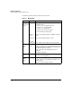
The following table describes the LEDs on the front panel.
Table C-1. Module LEDs
Module LED State Meaning
Module
Status
1
(green/
orange)
1.Indicates HDD and CF Status as well.
Flashing
green
Solid green
Flashing/
solid orange
When the module is first installed, this LED follows the
following sequence:
1. Green for ~15s - The module has power.
2. Orange for ~11s - Testing the LED.
3. Green for ~4s - Starting self-test.
4. Orange for ~30s - Self-test in progress.
5. Off - The module is booting the OS.
Service OS or ONE-app software is initializing or shutting
down.
Service OS or ONE-app software is ready.
Error condition. See the switch log for more information.
Module
Locator
(blue)
Flashing/
solid
Solid during boot only when the module is inserted into a
chassis, soft reboots do not enable this LED. Used to locate
a specific module in an area full of chassis. Enabled by using
the following switch CLI command:
services <slot ID> locater <blink [duration] | off | on
[duration]>
This LED is off by default.
HDD Activity
(green)
Flashing
Off
The drive is reading/writing.
The drive is not reading/writing.
Network
Activity
(green)
Flashing
Off
There is network activity on one or both internal ports.
If either of the ports fails, the Module Status LED is set to
flashing orange.
There is no network activity on either port.