
Field Replaceable Units (FRU) Guide, HP Advanced and Extended Services zl Modules 2011-11


Table Of Contents
7
Hardware Replacement Procedures
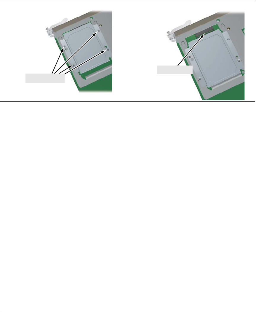
4. Slide the HDD back to disconnect it.
3.
Retaining Screws
4.
Disconnected
Figure 4b. Steps for Replacing the Module’s Disk Drive
5. Using the disk drive mounting brackets, lift
the HDD from the frame
(Lower Deck) or the four standoffs (Upper Deck).
6. Position the new HDD so that the
connector on the HDD and the
connector on the module board are aligned.
7. Slide the new HDD forward to engage the conne
ctor. The four holes in
the HDD’s mounting brackets should align with the mounting holes in the
module’s mounting frame or the four standoffs.
8. Re-install the four retaining screws. If appli
cable, remove the cover(s)
from the slot(s) where the module will be re-installed. Re-install the
module into the switch.
9. Use an equal amount of pressure and push both extractor handles closed
to completel
y seat the module.
10. Re-tighten the retaining screw
s to secure the module.
11. Now please refer to “Restoring Product Operation” on page 12 for the
next steps to restore full software operation of your AllianceONE zl
Mo
dule product. Look for the section that applies to your product, and
“After HDD Replacement”.