Getting Started Guide ProCurve Wireless EDGE Services zl Modules www.procurve.
© Copyright 2007 Hewlett-Packard Development Company, L.P. The information contained herein is subject to change without notice. Publication Number 5991- 8616 July 2007 Applicable Products ProCurve Wireless Edge Services zl Module (J9051A) ProCurve Redundant Wireless Edge Services (J9052A) zl Module Disclaimer HEWLETT-PACKARD COMPANY MAKES NO WARRANTY OF ANY KIND WITH REGARD TO THIS MATERIAL, INCLUDING, BUT NOT LIMITED TO, THE IMPLIED WARRANTIES OF MERCHANTABILITY AND FITNESS FOR A PARTICULAR PURPOSE.
Contents Introduction . . . . . . . . . . . . . . . . . . . . . . . . . . . . . . . . . . . . . . . . . . . . . . . . . . . . . . 1 Building a Wireless LAN System . . . . . . . . . . . . . . . . . . . . . . . . . . . . . . . . . Wireless Services-Enabled Switch . . . . . . . . . . . . . . . . . . . . . . . . . . . . . VLANs . . . . . . . . . . . . . . . . . . . . . . . . . . . . . . . . . . . . . . . . . . . . . . . . . . Radio Ports . . . . . . . . . . . . . . . . . . . . . . . . . . . . . . . . . . . . .
Introduction Introduction This Getting Started Guide supports the following ProCurve zl Modules: ■ ProCurve Wireless Edge Services zl Module (J9051A). ■ ProCurve Redundant Wireless Edge Services zl Module (J9052A). The ProCurve Wireless Edge Services zl Module (Module) enables a ProCurve Switch 5400zl Series or 8200zl Series to operate with ProCurve Radio Ports as a centrally-administered wireless LAN system.
Introduction A wireless LAN system can provide these services: ■ Association—Mobile users must be able to locate and connect to the wireless network. ■ Authentication—Typically, users and the wireless access provider should authenticate each other so that each knows that it is connecting to the correct peer. ■ Encryption—Wireless network traffic may be encrypted to protect it from interception.
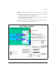
Introduction When a radio port is not connected directly to a wireless services-enabled zl switch: ■ the Radio Port VLAN must be configured on any switch between the radio port and the wireless services-enabled switch. ■ the radio port must be an untagged member of the Radio Port VLAN on the switch where it is connected. The illustration below shows VLAN requirements when using a radio port attached to an infrastructure, PoE-capable switch.
Introduction The refers to the slot in the zl Switch where the Module is located. Setting the VLANs in the Module does not set the VLANs in the zl Switch. Normally, the administrator will set the VLANs in the zl Switch first, then set the VLANs in the Module to correspond with the switch VLAN settings.
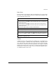
Introduction Radio Ports ProCurve Radio Ports provide the radio-based infrastructure to support wireless client connectivity and RF environment sensing and reporting. The table below summarizes their features. RADIO PORTS A radio port has 1 or 2 radios. ProCurve radio ports are: • ProCurve Radio Port 210 (J9004A) - Single-radio (802.11b/g) radio port; embedded 2.
Introduction WLANs RADIUS Authentication • 802.1X EAP • Web Auth (open) for hotspots • RADIUS-based ACLs using ProCurve Identity Driven Management Encryption • WEP • WPA/WPA2-TKiP • WPA2-AES • WPA2/AES-TKIP (802.11i Mixed Mode) WLAN Configuration Modes • Up to 16 WLANs can be configured per Radio.
Introduction Managing a Wireless LAN System An administrator uses a wireless services-enabled zl Switch to manage radio ports in a Wireless LAN System from one centralized interface. This provides the following: ■ System-wide configuration, enabling coordinated configuration of WLAN policies, and security across multiple radio devices. ■ System-wide view, providing security and unapproved-AP detection.
Getting Started ■ A Module by default does not participate in any Redundancy Group and is standalone. For a set of Modules to become a Redundancy Group, the administrator must configure each of the Modules. Multiple groups may be formed and operated independently. Each group is identified by a unique Group ID. ■ A Redundancy Group consists of a primary and one or more redundant Modules, up to a total of 12 Modules. The additional redundant Modules add bandwidth as well as network resiliency.
Getting Started Step 1 - Review the equipment list, connect the equipment, verify the ProCurve zl Switch software. The following is an example equipment list for building a wireless LAN system with a wireless services-enabled switch. ■ ■ ■ ■ ■ ■ ProCurve zl Switch (such as 5406zl, 5412zl, or 8212zl). ProCurve Module (J9051A). ProCurve Radio Port 230 (J9006A) or 210 (J9004A). ProCurve zl Modules for wired connectivity, for example, ProCurve Switch zl 24 port Gig-T PoE Module (J8702A).
Getting Started Step 2 - Boot up the system. 1. For zl switch LED indications during boot up, refer to the zl switch Installation and Getting Started Guide supplied with the switch. When the switch completes self-test, the Power LED stays on, and the Fault, Locator, and Test LEDs are off. 2. The port LEDs on the switch modules go through their self-test. After self-test, if a port is connected to an active network device, its Link LED stays on and its Mode LED behaves according to the mode selected.
Getting Started Connected at 9600 baud HP J8697A ProCurve Switch 5406zl Firmware revision K.12.40 Copyright (C) 1991-2007 Hewlett-Packard Co. All Rights Reserved. RESTRICTED RIGHTS LEGEND Use, duplication, or disclosure by the Government is subject to restrictions as set forth in subdivision (b) (3) (ii) of the Rights in Technical Data and Computer Software clause at 52.227-7013. HEWLETT-PACKARD COMPANY, 3000 Hanover St.
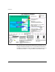
Getting Started Step 4 - Launch Module’s Web browser interface. 1. Open a browser on the network connected PC, and type in the URL for the Module. 2. A Java applet is required to open the Module web browser. If the PC does not have this software, JVM will be automatically downloaded to the PC via an Internet connection. 3. If a "Warning-Security" screen appears, click Yes to proceed. 4. The illustration below is the Wireless Edge Services zl Module login page.
Getting Started The Device Information screen for the Module appears. Note the message in the upper right corner of the screen, Country Code not set. Use Network setup page to set Country Code. See See “Step 5 - Set up Country Code and other wireless network administrative data” on page 16. below. Note This device requires the administrator to select the appropriate Country Code during the initial setup of the Module.
Getting Started The Device Information screen also provides the administrator with additional information, as noted below. These definitions are also available on the Help menu. System: • System Name - A user-specified name for the module. • Location - A user-specified description for the location of the module. • Contact - A user-specified name for an administrator of the module. • Uptime - System Uptime is the current uptime for the system name defined within the System Name field.
Getting Started The Web browser interface screens have the following features: ■ A navigation panel on the left, which allows the administrator to setup and manage the Module. This publication will use the following format to identify a screen: Navigation Pane Tab #1 > Navigation Pane Tab #2 (if applicable) > Screen Tab (in the middle of screen, if applicable). For example, to change the password, the administrator is directed to screen, Management > WebUsers > Local Users.
Getting Started Change Password It is recommended the administrator change the default Password. 1. Select Management > Web-Users > Local Users. On this screen highlight manager and select Edit. 2. Enter a password, using the Password and the Confirm Password fields. Select OK. The new password is assigned and will be required the next time you log on.
Getting Started The Country Code and administrative data is now displayed on the Device Information screen: 17
Getting Started Step 6 - Verify Radio Port adoption. To verify that the radio ports have been adopted by the Module, select Device Information > Radio Adoption Statistics. If some of the radio ports are not found on this screen, check the status of the LEDs on the missing radio ports. • If both the LEDs blink about once every 5 seconds, the Radio Port is adopted and ready for use. • If the amber light is continuously blinking, with the green light out. the radio port is in the unadopted mode.
Getting Started Configuration 1 - Normal Mode with one WLAN and two radio ports. 1. Configure a WLAN. While many optional settings can be configured, a WLAN requires an SSID, a VLAN in which traffic will be forwarded, and security options for authentication and encryption. To configure a WLAN, go to Network Setup > WLAN Setup > Configuration. 2. Click and highlight Index 1. Select Edit or double-click on the Index line and an Edit screen appears.
Getting Started a radio (single click), the WLAN Assignment is shown on the far right of the screen. By holding down the right button of the mouse, and scrolling down all of the radios, the WLAN Assignment for all radios is shown on the right side of the screen. The screen will list all available WLANs (up to 16 WLANs in Normal Mode). In this example, all of the radios are assigned to the WLAN with the Faculty1 SSID, and operate on BSSID1. 6.
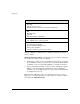
Getting Started Configuration 2 - Normal Mode with five WLANs and two radio ports. This examples uses the following WLAN settings: WLAN SSID Name VLAN Authentication Encryption 1 Faculty1 Faculty 1 none 64WEP 2 Students2 Students 2 none none 3 Science3 Science Dept 3 802.1X EAP 64WEP 4 ADM4 Administration 4 802.1X EAP 128WEP 5 Math5 Math Dept 3 802.1X EAP 128WEP 1. Select Network Setup > WLAN Setup > Configuration.
Getting Started 2. Note 22 To review the BSSID and SSID assignments, select Network Setup > Radio > WLAN Assignments. On the right side of the screen, the 5 WLAN(SSIDs) are noted and their assignments to the 4 BSSIDs. Note that BSSID1 is assigned to Faculty1 and Math5, which correspond to SSID1 and SSID5. SSID Math5 is shared on BSSID 1, but is not beaconed by the Radio Port. Only SSID Faculty1 is beaconed on BSSID1. RP radios send beacon frames to announce the WLANs that they support.
Getting Started Configuration 3 - Adding redundancy. In this example,the following modules will be set up in a Redundancy Group. ■ ProCurve Wireless Edge Service zl Module (J9051A). ■ ProCurve Redundant Wireless Services zl Module (J9052A). Note: For the optimal redundancy and protection, the preferred setup is for the J9051A and J9052A to be installed in different chassis. However, these modules may be installed in the same chassis. 1.
Loading New Module Software 3. The next step is to add the IP address of the redundant member. Select the screen Network Setup > Redundancy Group> Member. Select Add and a pop-up screen appears. Enter the IP address of the new Group member (J9052A). Select OK to return to the main screen. 4. Next, repeat these steps with the J9052A module, using its IP address for the Interface IP, and the IP address of the J9051A module as the Member.
Loading New Module Software 2. Locate the new software version in a TFTP or FTP server folder. 3. Select the Upgrade Software button, and the Upgrade Screen appears. Enter the appropriate information: – Enter the update filename (for example, "WT.01.03.img") – Select TFTP – Enter IP address of the TFTP server (for example, 192.168.2.3) – Enter the path to the file on that server, or "/" if it is located in the TFTP root 4. Select Do Upgrade. 5.
Restore Factory Defaults Setting 6. After about 1 minute, the Status message, "Software has been successfully upgraded" appears. 7. The screen Management>System Maint. - Software displays the new software. On the next boot, the new software is selected. 8. To reload the new software, go to the Management screen, and click the Reload button. 9. A message appears to confirm the action to Reload and logoff the system, and allows you to select booting from Primary or Secondary.
Technical information in this document is subject to change without notice. © Copyright 2007 Hewlett-Packard Development Company, L.P. Reproduction, adaptation, or translation without prior written permission is prohibited except as allowed under the copyright laws.