HP Advanced Services v2 zl Module Installation Guide Abstract This document describes how to install and initially configure the Advanced Services v2 zl Module (J9857A and J9858A). This product is hereafter referred to as module. See also the Advanced Services v2 zl Module Configuration Guide.
© Copyright 2013 Hewlett-Packard Development Company, L.P. The information contained herein is subject to change without notice. The only warranties for HP products and services are set forth in the express warranty statements accompanying such products and services. Nothing herein should be construed as constituting an additional warranty. HP shall not be liable for technical or editorial errors or omissions contained herein. Acknowledgments Microsoft® and Windows®, are U.S.
Contents 1 Preparing for installation.............................................................................4 Identifying module components..................................................................................................4 Switch LEDs.............................................................................................................................5 Serial number....................................................................................................................
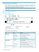
1 Preparing for installation The HP Advanced Services v2 zl Module is a module that you can plug into switch chassis such as the 5406zl, 5412zl, 8206zl, and 8212zl. Read the switch documentation to prepare the switch before you plug in the HP Advanced Services v2 zl Module. NOTE: The HP Advanced Services v2 zl Module requires at least Version K.15.14.xxxx or later on the switch. Identifying module components Front panel and LEDs Figure 1 Module front panel 1. Module Status LED 2.
LED State Meaning Locator (blue) Solid The services locator on command was issued to assist in finding the module. Flashing The services locator blink command was issued to assist in finding the module. NOTE: Flashing duration defaults to 30 minutes, but can be set anywhere from 1 minute to 1440 minutes. USB Enable LED (green) HDD/SSD Activity (green) Network Activity (green) Off Default state.
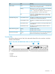
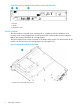
Figure 3 Test, Fault, and Module Status LEDs on a Series 82xxzl switch 1. Fault LED 2. Test LED 3. Module Status LEDs Serial number The serial number is required when contacting HP or a reseller for warranty assistance or for coverage under a service agreement. Record the serial and product number for future reference. Refer to the warranty information for coverage details. The serial number for the module is located on the bottom of the module.
Installation precautions • Static electricity can severely damage the electronic components on the module. When handling and installing the module, follow these procedures to avoid damage from static electricity: • Handle the module by its bulkhead or edges and avoid touching the components and the circuitry on the board.
2 Installing WARNING! This is a general procedure. It is the installer’s responsibility to perform the installation in accordance with local electrical code and regulations. You can install a maximum of four modules in a 5406zl, three modules in 8206zl, and up to six modules in 5412zl and 8212zl chassis, assuming that no other service modules are installed in the chassis. See “Environmental specifications” (page 7) for additional restrictions.
is installed while the switch already has power. The switch and module LEDs indicate if the module has passed the self-test, as described in the following table. NOTE: At power-on and during module self-tests, all LEDs turn on for at least 7 seconds and go through their range of colors. Once the self-tests have completed, all LEDs return to behaving normally. LED Location of LED Display for a properly installed module Test Switch Off.
3 Initially connecting and configuring This chapter describes how to connect to the switch, configure the switch for the module, and then perform initial module configuration. Finally, information on restarting and resetting the module is provided. Connect to the switch Although full information on the switch CLI (command line interface) is provided in the switch documentation, the basic switch CLI commands needed to work with the module are provided in this document.
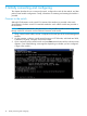
4. Press any key to continue. The switch CLI prompt appears. It looks similar to: HP-8212zl# NOTE: If the switch menu appears instead, return to the top-level menu and select Command Line (CLI). The switch CLI prompt appears, similar to: HP-8212zl# Verify switch software version Before configuring the module, verify that the switch software version is at least Version K.15.14. 1. At the switch CLI prompt, enter: show version 2. The software version information is displayed: Image stamp: ...
2. 3. Press Enter. Select Switch Configuration. 4. From the Switch Configuration menu, select VLAN Menu. 5. Select VLAN Names. 6. Add VLANs to the module. The example shows two VLANs, with names zlModule_VLAN1 and zlModule_VLAN2.
7. Select VLAN Port Assignment. 8. 9. Select Edit and then use the arrow keys to select the DEFAULT_VLAN column of port D1i. Use the space bar to change values and the arrow keys to move between items. Moving from left to right, set port D1i to No, Untagged, No. Set port D2i to No, No, Untagged. Ports D1i and D2i should now look like this: 10. Use the arrow keys to select the DEFAULT_VLAN cell for port A1.
11. Select Save when finished, and then select Return to Main Menu. Install VMware vSphere You can install the VMware vSphere from a CD, DVD, USB Flash, or through Preboot Execution Environment (PXE). For more information about the installation options, see VMware vSphere Installation and Setup Guide. Boot from a CD/DVD The following procedures describe how to download the VMware vSphere ISO image, create a boot CD/DVD and boot from the CD/DVD. 1. Download the VMware vSphere 5.
7. To switch to the module serial console from the switch CLI prompt, enter: services serial The module boots from the CD/DVD image installed in the CD/DVD drive. You can now install VMware vSphere 5.5 ISO image on the Advanced Services v2 zl Module. Follow the instructions from the VMware’s Installation and Setup Guide to install the image. Boot from a USB flash drive The following procedures describe how to download the VMware vSphere ISO image, create a boot USB flash drive and boot from it.
4 Support and other resources Online documentation You can download documentation from the HP Support website at: www.hp.com/support/manuals. Search by product number or name. Contacting HP For worldwide technical support information, see the HP support website: www.hp.
A Regulatory information This product is a Class A device, pursuant to Part 15 of the FCC Rules. For important safety, environmental, and regulatory information, see Safety and Compliance Information for Server, Storage, Power, Networking, and Rack Products, available at www.hp.com/ support/Safety-Compliance-EnterpriseProducts.
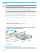
B Replacing hardware components Replacing or removing a module HP recommends that the module be shut down before removing or replacing it. The preferred method of shutting down the module is through the CLI: services shutdown Where identifies the switch slot containing the module. A confirmation message appears. Respond with "y" to continue. It is possible to "hot-swap" one module for another of the same type.
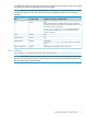
Figure 6 Replacing the module HDD or SSD 1. Module retaining screws 3. HDD or SSD retaining screws 2. Extractor handles 4.