
HP Advanced Services v2 zl Module Installation Guide

B Replacing hardware components
Replacing or removing a module
HP recommends that the module be shut down before removing or replacing it. The preferred
method of shutting down the module is through the CLI:
services <slot-id> shutdown
Where <slot-id> identifies the switch slot containing the module. A confirmation message
appears. Respond with "y" to continue.
It is possible to "hot-swap" one module for another of the same type. That is, replace one module
with another while the switch is still powered on without interrupting the operation of the rest of
the switch ports. If the modules are not the same type, the switch must be rebooted.
CAUTION: It is mandatory for you to wait at least five seconds between removing a module and
re-installing it or replacing it with another.
To replace one module with another, or to remove a module without replacing it, use the following
procedure:
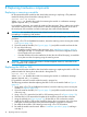
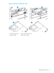
1. Using a Torx T-10 or flat-bladed screwdriver, loosen the retaining screws securing the module
(1 in Figure 6 (page 19)).
2. Open the extractor handles (2 in Figure 6 (page 19)) and pull the module out from the slot.
3. Do one of the following:
• If installing another module of the same type, go to “Installation procedure” (page 8)
and begin with step 2. A switch reset is not required. The current configuration in that
slot will apply to the new module.
• If another module will not be installed in the slot (the slot will be left empty), re-install the
cover plate over the slot opening using the retaining screws.
CAUTION: For proper cooling and reduction of electromagnetic emissions, ensure that a slot
cover is installed on all unused slots.
Replacing the HDD or SSD
HP recommends that the module be shut down before removing or replacing the HDD or SSD. The
preferred method of shutting down the module is through the CLI:
services <slot-id> shutdown
Where <slot-id> identifies the switch slot containing the module. A confirmation message
appears. Respond with "y" to continue.
It is possible to remove the module while the switch is powered on.
The following procedure describes replacing the HDD or SSD in the module. Refer to Figure 6
(page 19).
1. Using either a Torx T-10 or flat-bladed screwdriver, loosen the retaining screws securing the
module (1 in Figure 6 (page 19)).
2. Open the extractor handles (2 in Figure 6 (page 19)) and pull the module out from the slot
and turn it over.
3. Using a Torx T-10, remove the four HDD or SSD retaining screws (3 in Figure 6 (page 19)).
4. Slide the HDD or SSD towards the faceplate of the module to disconnect the connectors.
5. Using the pull tab (4 in Figure 6 (page 19)), lift the HDD or SSD out from the module.
6. Install the new HDD or SSD into the module by placing the non-connector side in first, then
sliding the connector side back (away from the faceplate) to engage the connectors.
7. Re-install the four HDD or SSD retaining screws using a Torx T-10 screwdriver.
8. Re-install the module into the switch. Refer to “Installation procedure” (page 8) and begin
with step 2.
18 Replacing hardware components