
HP Advanced Services v2 zl Module Installation Guide


2 Installing
WARNING! This is a general procedure. It is the installer’s responsibility to perform the installation
in accordance with local electrical code and regulations.
You can install a maximum of four modules in a 5406zl, three modules in 8206zl, and up to six
modules in 5412zl and 8212zl chassis, assuming that no other service modules are installed in
the chassis. See “Environmental specifications” (page 7) for additional restrictions.
NOTE: If you insert the replacement module into a slot that previously contained a module of a
different type, you will need to perform a switch reset. A module of a different type is any module
other than the MSM775 zl Controller (J9840A), Advanced Services v2 zl Module with HDD
(J9857A), or Advanced Services v2 zl Module with SSD (J9858A).
Installation procedure
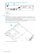
1. Use a Torx T-10 or flat-bladed screwdriver to loosen the screws in the cover plate over the slot
where the module is to be installed. Remove the cover plate and store it for possible future
use.
2. Hold the module by its bulkhead, taking care not to touch the connectors or components on
the boards.
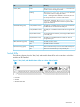
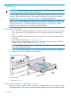
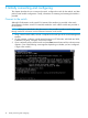
3. Open the extractor handles (1 in Figure 5 (page 8)).
4. Align the lower PC board with the card guide in the chassis, insert the module, and slide it
into the slot until it is fully inserted (2 in Figure 5 (page 8)).
NOTE: Note: The switch has low force, high-performance connectors. Avoid using excessive
force when installing the module.
5. Once the contacts have engaged, use the extractor handles to seat the module completely.
6. Tighten the screws on the front panel of the module.
Figure 5 Module being installed
1. Extractor handles
2. Module being inserted
Verifying the module is installed correctly
When the module is installed correctly, it undergoes a self-test that takes thirty to forty-five seconds.
This happens both when the switch is powered on after installing the module and when the module
8 Installing