HP Advanced Services zl Module with Citrix XenServerTM Platform Installation and Getting Started Guide
© Copyright 2011 Hewlett-Packard Development Company, L.P. The information contained herein is subject to change without notice. All Rights Reserved. This document contains proprietary information, which is protected by copyright. No part of this document may be photocopied, reproduced, or translated into another language without the prior written consent of HewlettPackard.
Contents 1 Hardware Installation Overview . . . . . . . . . . . . . . . . . . . . . . . . . . . . . . . . . . . . . . . . . . . . . . . . . . . . . . 1-1 Module Hardware . . . . . . . . . . . . . . . . . . . . . . . . . . . . . . . . . . . . . . . . . . . . 1-2 Module software . . . . . . . . . . . . . . . . . . . . . . . . . . . . . . . . . . . . . . . . . . . . . 1-3 Updating the Switch Software . . . . . . . . . . . . . . . . . . . . . . . . . . . . . . . . . . . 1-4 Installing the Module . . . . . . . .
3 Troubleshooting Quick Tips . . . . . . . . . . . . . . . . . . . . . . . . . . . . . . . . . . . . . . . . . . . . . . . . . . . . . 3-1 The module fails to boot . . . . . . . . . . . . . . . . . . . . . . . . . . . . . . . . . . . . . . . 3-1 XenServer not displayed in “show services” output . . . . . . . . . . . . . . . . . . 3-1 Interpreting “hardware ready” status output . . . . . . . . . . . . . . . . . . . . . . . . 3-2 Scrolling text when using “services tech” command . . . . . . . . . . . . . . .
Replacing Field Replaceable Units (FRUs) . . . . . . . . . . . . . . . . . . . . . . . . . C-6 D Software Components Updating Switch Software . . . . . . . . . . . . . . . . . . . . . . . . . . . . . . . . . . . . . . . D-1 Updating the Service OS . . . . . . . . . . . . . . . . . . . . . . . . . . . . . . . . . . . . . . . . D-4 Updating Service OS via FTP . . . . . . . . . . . . . . . . . . . . . . . . . . . . . . . . . . D-4 Updating Service OS via USB . . . . . . . . . . . . . . . . . . . . . . . . . .
ping . . . . . . . . . . . . . . . . . . . . . . . . . . . . . . . . . . . . . . . . . . . . . . . . . . . . . E-10 show assigned-mac-address . . . . . . . . . . . . . . . . . . . . . . . . . . . . . . . . . . . E-10 show chassis . . . . . . . . . . . . . . . . . . . . . . . . . . . . . . . . . . . . . . . . . . . . . . E-10 show images . . . . . . . . . . . . . . . . . . . . . . . . . . . . . . . . . . . . . . . . . . . . . . E-10 show ip . . . . . . . . . . . . . . . . . . . . . . . . . . . . . . . . . .
1 Hardware Installation Overview The HP Advanced Services zl Module with Citrix XenServer™ Platform (J9747A) has XenServer pre-installed at the factory, and is ready for module installation in an HP E5400 zl or E8200 zl Series switch. The module automatically boots XenServer when installed in an HP E5400 zl or E8200 zl Series switch. You access the XenServer xsconsole management interface and the shell interface directly through the switch CLI.
Hardware Installation Overview If you want to start immediately, move to “Updating Switch Software” on page D-1 in Appendix D, “Software Components”. You can obtain more details about the module in “Module Hardware” on page 1-2 and “Module software” on page 1-3. Table 1-1.
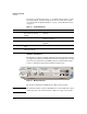
Hardware Installation Overview The module connects to the switch through two internal 10 Gigabit ports. In the switch CLI, the ports are referenced as 1 and 2, in which is the letter for the slot in which the module is installed (for example, C1 and C2). These ports carry network traffic to and from the module. The module relies on the switch for its power and network connectivity.
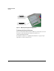
Hardware Installation Overview Hard DISK (HD) Integrated XenServer host Compact Flash (CF) Service OS Figure 1-2. Module Operating System and Application Updating the Switch Software If you need to install the HP zl switch that will house your module, refer to the Installation and Getting Started Guide for the switch or at www.hp.com/networking/support. To install new software, see “Updating Switch Software” on page D-1 (in Appendix D, “Software Components”).
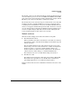
Hardware Installation Installing the Module Installing the Module Installation Precautions Static electricity can severely damage the electronic components on the module. When handling and installing the module, follow these procedures to avoid damage from static electricity: • Handle the module by its bulkhead or edges and avoid touching the components and the circuitry on the board.
Hardware Installation Installing the Module Installation Procedure 1. Confirm that the switch time is set and corret as described in the Installation and Getting Started Guide for the switch at www.hp.com/networking/support. 2. If installing in an unused slot, use a Torx T-10 or flat-bladed screwdriver to unscrew the screws in the cover plates over the slot where you will install the module. Store the cover plates for possible future use. 3.
Hardware Installation Installing the Module The procedure to replace or remove a module is described in “Replacing or Removing a Module” on page C-5 in Appendix C: “Hardware Components.” Verifying That the Module Is Installed Correctly If you have installed the module in a powered off HP zl switch, power up the switch. After the switch powers up, the module will begin to power up. If you have installed the module in a powered on switch, the module begins to power up immediately.
Hardware Installation Environmental Specifications Environmental Specifications Table 1-3. Environmental Specifications Temperature Operating* Non-Operating 0C to 45C (32F to 113F) -10C to 65C (-10F to 149F) Relative humidity (non-condensing) 15% to 90% at 40C (104F) 15% to 90% at 65C (149F) Maximum altitude 3.0 km (10,000 ft) 4.6 km (15,000 ft) Table 1-4.
Hardware Installation Environmental Specifications Figure 1-4.
Hardware Installation Environmental Specifications 1-10
2 Management Getting Started At this point, your HP zl switch should be installed, and the HP Advanced Services zl Module with Citrix XenServerTM should be installed within it. This section guides you through the next steps that must be completed before you can access the module. XenServer Defaults Set at Installation XenServer Setting Installed Setting Purpose and Use Primary Management Interface Automatic configuration (DHCP) Connects to your network and carries management traffic.
Management Getting Started Identifying the Module Interfaces The HP Advanced Services zl Module has three interfaces. Internal interface 1 and 2—These two 10 Gigabit Ethernet interfaces connect to the HP zl switch backplane and provide the LAN connection for the XenServer that runs on the module. You cannot see these interfaces on the module’s front panel (they are internal to the module), but the HP zl switch manages the interfaces just like other switch ports.
Management Getting Started Displaying the XenServer Host Module’s Chassis Slot The show modules command from the switch CLI displays whether or not a module running a XenServer host is present in a zl switch, and the switch slot where it is installed.
Management Getting Started Connecting to a Management Interface You have several options for reaching the XenServer OS that runs on the module: 2-4 Management Interface Description How to access... XenServer shell Command Line Interface (CLI) Allows you to • From the switch CLI manager/configure administer XenServer context, enter services tech. using the Linux-based • From an SSH session to the Primary xe commands.
Management Getting Started Accessing XenServer Shell 1. At the switch CLI Manager/Configure context, enter Services tech followed by one or more carriage returns. HP Switch(config)# services c tech Citrix XenServer Host 5.6.100-46766p System Booted: 2011-06-01 02:14 Your XenServer Host has now finished booting. To manage this server please use the Citrix XenCenter application. You can install XenCenter for Windows from the XenServer installation media.
Management Changing the Default Password Accessing the xsconsole 1. See “Accessing XenServer Shell” on page 2-5 and complete steps one through three. 2. At the XenServer shell prompt, type xsconsole. The menu-driven interface of the xsconsole appears. 3. Select Quit from the top-level menu to return to the XenServer shell. 4. Typing exit closes the XenServer shell and logs you out. Type Control-z to return to the switch CLI. Accessing the Primary Management Interface Using SSH 1.
Management Setting the Time on the XenServer You also can use the XenServer shell to change the password. For more information, search for “How to Change the Root Password Of A XenServer” in the Knowledge Center on the Citrix Support site (http://support.citrix.com). Setting the Time on the XenServer Using the correct system time on the module is a pre-requisite for minimizing conflicts and accessing some advanced features, such as pools, offered by Citrix.
Management Installing XenCenter Important Attempting to shut down XenServer using methods other than XenServer management tools, such as the switch CLI services shutdown or reload commands, may corrupt the XenServer. Installing XenCenter HP recommends installing XenCenter to manage your XenServer host module.
3 Troubleshooting Quick Tips The module fails to boot Issue: The module fails to boot or the Module Status LED is not solid green. Caution Be patient. The module takes several minutes to boot initially, and you must not interrupt this process. After waiting for several minutes: • Check the switch’s software version. It must be K15.05 or greater.
Troubleshooting Quick Tips This message appears when there are no other services installed in the switch chassis. The XenServer host module is independent of the switch services, so it is not listed. HP Switch# show services Installed Services Slot Index Description E 1. Services zl Module E 2. Threat Management Services zl Module HP Switch# Name services-module tms-module This message appears when other services are installed in the switch.
Troubleshooting Quick Tips Here is what you would see running the above command for a XenServer host module in slot C: HP Switch# show services c details Status and Counters - Services Module C Status HP Services zl Module J9685A Versions Current status : A.01.09 : hardware ready Description Version Status ------------------------------------------ ------------------- --------Services zl Module hardware HP Advanced Services zl Module with JC9747A 5.6.
Troubleshooting Accessing Troubleshooting Options minutes. If you wait, it may take a minute or two to complete the boot process. The screen may at times stop scrolling, but this is normal, so be patient. DHCP address not received • Verify that the module’s internal port 2 is in the correct VLAN. Enter vlan untagged 2 in the switch CLI mange/configure context to move this port to the VLAN where the DHCP server can be accessed.
Troubleshooting Accessing Troubleshooting Options Booting the Service OS There is a Service OS that is useful for hardware and other troubleshooting functions that is not loaded when XenServer boots from the HD. Once in this context, show commands will be available to you as described in Appendix E: “Service OS Command-Line Reference”. Booting the Service OS when the XenServer is running 1. Important Use a XenServer management interface to shut down the XenServer.
Troubleshooting HP Customer Support Services HP Switch(config)# services c tech Note: 2. At the SvsOS prompt, log in using admin for user name and admin for password. 3. Once in tech mode, use the corresponding keyboard number to select from the Admin Menu of available troubleshooting options. Option Troubleshooting function 1 Exits the Service OS tech mode. 2 Runs hardware diagnostic tests. Tests include tests of the x86 subsystem, the hard drive, and the compact flash.
Troubleshooting For More Information on XenServer For More Information on XenServer Visit the Citrix web site for product information, technical support, software updates and upgrades, and licensing information: For more information on XenServer, visit www.citrix.com/xenserver. For the most up-to-date Citrix product documentation http://support.citrix.com/proddocs/index.jsp. For Citrix Support, visit http://support.citrix.com.
Troubleshooting For More Information on XenServer 3-8
EMC Regulatory Statements A EMC Regulatory Statements U.S.A. - FCC Class A This equipment has been tested and found to comply with the limits for a Class A digital device, pursuant to Part 15 of the FCC Rules. These limits are designed to provide reasonable protection against interference when the equipment is used in a commercial environment.
EMC Regulatory Statements Japan - VCCI Class A Korea Taiwan European Community Declaration of Conformity This product is designed for operation with the HP ProCurve switches that have zl module slots. Refer to the Declarations of Conformity included in the Installation Guides for those products.
Waste Electrical and Electronic Equipment (WEEE) Statements B Waste Electrical and Electronic Equipment (WEEE) Statements Disposal of Waste Equipment by Users in Private Household in the European Union This symbol on the product or on its packaging indicates that this product must not be disposed of with your other household waste.
Waste Electrical and Electronic Equipment (WEEE) Statements Laitteiden hävittäminen kotitalouksissa Euroopan unionin alueella Jos tuotteessa tai sen pakkauksessa on tämä merkki, tuotetta ei saa hävittää kotitalousjätteiden mukana. Tällöin hävitettävä laite on toimitettava sähkölaitteiden ja elektronisten laitteiden kierrätyspisteeseen.
Waste Electrical and Electronic Equipment (WEEE) Statements Smaltimento delle apparecchiature da parte di privati nel territorio dell'Unione Europea Questo simbolo presente sul prodotto o sulla sua confezione indica che il prodotto non può essere smaltito insieme ai rifiuti domestici. È responsabilità dell'utente smaltire le apparecchiature consegnandole presso un punto di raccolta designato al riciclo e allo smaltimento di apparecchiature elettriche ed elettroniche.
Waste Electrical and Electronic Equipment (WEEE) Statements Descarte de Lixo Elétrico na Comunidade Européia Este símbolo encontrado no produto ou na embalagem indica que o produto não deve ser descartado no lixo doméstico comum. É responsabilidade do cliente descartar o material usado (lixo elétrico), encaminhando-o para um ponto de coleta para reciclagem.
Hardware Components Front Panel Buttons, LEDs, and Connectors C Hardware Components Front Panel Buttons, LEDs, and Connectors This section describes the different buttons, LEDs, and connectors on the front panel of a module: ■ Caution Module Shutdown button—This button will shut down the module. It should not be used for this purpose. Instead, use the hypervisor utilities to gracefully shutdown the guest VMs and host. A hard shutdown can introduce the risk of hard disk drive (HDD) file corruption.
Hardware Components Internal Ports Table C-1. Module LEDs (Continued) Module LED State Meaning Module Locator (blue) Flashing/ solid Solid during boot only when the module is inserted into a chassis, soft reboots do not enable this LED. Used to locate a specific module in an area full of chassis. Enabled by using the following switch CLI command: services locater
Hardware Components Serial Numbers Disk drive serial and product numbers Figure C-1. Locating the disk drive serial number The serial number for the module is located on the back left corner of the module (Figure C-2). Module serial number SN: SGxxxxxxxx Figure C-2.
Hardware Components Switch LEDs Switch LEDs The following figures show the Test, Fault, and Module Status LEDs on the switches the module can be installed in. Test LED Fault LED Module Status LEDs Figure C-3. Test, Fault, and Module Status LEDs on an E5400 zl Series switch Fault LED Test LED Module Status LEDs Figure C-4.
Hardware Components Replacing or Removing a Module Replacing or Removing a Module It is highly recommended that the module be shutdown before replacing or removing it. To shut down the module, see “Shutting Down XenServer” on page 2-7. It is possible to “hot-swap” one module for another of the same type; that is, replace one module with another while the switch is still powered on, without interrupting the operation of the rest of the switch ports.
Hardware Components Replacing Field Replaceable Units (FRUs) Replacing Field Replaceable Units (FRUs) This module includes the following FRUs: ■ Disk Drive ■ Compact flash Please see the HP Advanced or Extended Services zl Modules Field Replaceable Units (FRU) Guide, which you can view or print from the HP networking Web site (www.hp.com/networking/support).
Software Components Updating Switch Software D Software Components Updating Switch Software Before installing the module, you must verify that the switch is running HP zl switch software version K.15.05 or later and update the software, if necessary. You must install the correct software version for the switch to recognize the module. 1. Visit the HP Web portal at www.hp.com/networking/support to check the version number of the latest module-compatible software. 2.
Software Components Updating Switch Software iii. When prompted, press [y]. • TFTP server—Follow these steps: i. Copy the file to a TFTP server that has network connectivity to the HP zl switch. ii. Enter this command from the HP zl switch CLI: HP Switch# copy tftp flash secondary iii. When prompted, press [y]. Note If you need to stop this command or another, press either [Ctrl-C] or [Ctrl-Z].
Software Components Updating Switch Software 6. When prompted to reboot the switch, press [y]. 7. When prompted to save the configuration, press [y] again. 8. After the switch reloads, reestablish your management session. Then enter this command to verify that the new software is running: HP Switch# show version You should see the following output. HP Switch# show version Image stamp: /sw/code/build/btm(ec_K_detroit_qaoff) May 6 2011 14:43:14 K.15.05.
Software Components Updating the Service OS Updating the Service OS There are two ways to update the Service OS: Note ■ via FTP: used when a local FTP server is accessible from the module ■ via USB: used when a local FTP server is not accessible from the module The process of updating the Service OS is faster if the switch is accessed via Telnet or SSH; the serial console slows down the writing of characters to the screen, causing a significantly slower installation speed, especially if the switch co
Software Components Updating the Service OS HP Switch(svcs-mod-C:SvcOS)# show images 5. Update the Service OS. HP Switch(svcs-mod-C:SvcOS)# update ServiceOS 6. Boot the Service OS: HP Switch(svcs-mod-C:SvcOS)# boot serviceOS System will be rebooted. Do you want to continue [y/n]? y 7.
Software Components Device Disable 9. Unmount the USB flash drive. HP Switch#(ssvcs-mod-C:SvcOS)# usb unmount 10. Remove the USB flash drive from the module. 11. For the rest of the procedure, go to Step 4. on page D-4. Device Disable The module offers improved security and reliability. In case there is no physical security on the chassis, the USB and the shutdown button can be disabled to prevent unauthorized or undesired access. Both the USB and the shutdown button are enabled by default.
E Service OS Command-Line Reference Overview Note: The commands described in this section are only available when the Service OS has been booted as described in “Booting the Service OS” on page 3-5. This chapter describes the commands provided by the command line interface (CLI) for the HP Advanced Services zl Module with Citrix XenServerTM (J9747A). This CLI is intended for basic monitoring and initial IP configuration.
Service OS Command-Line Reference Overview Syntax: show services details Vertical bars ( | ) separate alternative, mutually exclusive elements. Square brackets ( [ ] ) indicate optional elements. Braces ( < > ) enclose required elements. Angle brackets within square brackets ( [ < > ] ) indicate a required element within an optional choice. Angle brackets within angle brackets ( < < > > ) indicate a required element within a required choice.
Service OS Command-Line Reference Overview List Options for a Command You can also use the ? to view the options for a particular command. For example, you might enter: HP Switch# show ? Command Completion You can also use the Tab key to complete the current word in a command. To do so, type one or more consecutive characters in a command and then press [Tab] (with no spaces allowed).
Service OS Command-Line Reference Service OS Operator Context Commands Service OS Operator Context Commands The Service OS operator context allows restricted access to read-only commands on the Service OS of the module. To access this context, enter the following command from the host switch’s operator-level context: Syntax: services 1 Moves you to an OS context on the module. Replace with the letter for the lower chassis slot in which the module is installed.
Service OS Command-Line Reference Service OS Operator Context Commands Syntax: [no] page This command is available from all contexts. ping Use this command to send an ICMP echo to a specified destination. Syntax: ping < IP address > Replace with the IP address of the ping destination. For example: HP Switch(svcs-mod-:SvcOS)> ping 10.1.1.1 When you send ICMP echoes, the module displays the ping statistics to describe the types of responses the router receives.
Service OS Command-Line Reference Service OS Operator Context Commands show chassis This command shows the chassis slot in which the module resides. Syntax: show chassis show ip This command shows the module’s IP configuration. Syntax: show chassis show logging This command shows all of the logging information. You can view the following locally logged events.
Service OS Command-Line Reference Service OS Manager Context Commands Service OS Manager Context Commands The Service OS manager context allows restricted access to the Service OS of the module, providing only a limited number of commands. From this mode, you can download and install software. CLI access to the Service OS is designed primarily for blade maintenance, not for configuring the module. The Service OS context is used to complete basic setup and maintenance tasks.
Service OS Command-Line Reference Service OS Manager Context Commands Important In addition to those listed below, the Service OS also provides the following commands which you must not use unless so directed by an HP networking support agent: ■ delete ■ download ■ install ■ sync ■ uninstall ■ update ■ usb boot This command allows you to boot the XenServer. Syntax: boot ONE-app You will be prompted to continue.
Service OS Command-Line Reference Service OS Manager Context Commands ip This is the only configuration command available from the Service OS manager context. It allows you to configure an IP address and default gateway on the Service OS so that the module can communicate with an FTP server. To configure the module’s IP address, enter the following command: Syntax: [no] ip < dhcp | address > Use the dhcp option to configure the module to receive a dynamic IP address.
Service OS Command-Line Reference Service OS Manager Context Commands To uninstall a license on the module, enter the following command: Syntax: licenses unistall ping Use this command to send an ICMP echo to a specified destination. Syntax: ping < IP address > Replace with the IP address of the ping destination. For example: HP Switch(svcs-mod-SvcOS)# ping 10.1.1.
Service OS Command-Line Reference Service OS Manager Context Commands show ip This command shows the IP settings of the module Service OS (IP address and default gateway). Syntax: show ip show logging This command shows all of the logging information. To view the locally logged events, enter the following command: Syntax: show logging [-a] [-r] [-d] [option string] The log will be displayed with the most recent last, unless you specify otherwise.
Service OS Command-Line Reference Service OS Manager Context Commands E-12
Index State … C-1 Switch … C-4 Test … 1-7 C CLI commands … E-1 Command Line Interface (CLI) show version … D-1 Switch … C-2, D-1 Compact Flash … 1-3 M D maximum modules … 1-8 Module Front Panel … C-1 Module Shutdown … C-1 Device Disable … D-6 DHCP … 3-4 O E EMC Regulatory Statements … A-1 environmental specifications … 1-8 F operating systems … 1-3 Citrix XenServer Host … 1-3 HP service OS … 1-3 OS Updates … D-4 R front panel USB port … C-1 front panel port … C-1 Replacing the Disk Drive … C-6
USB slot HP zl switch … D-1 W warranty … 1-1 Waste Electrical and Electronic Equipment (WEEE) Statements … B-1 Z zl Switch … 1-5, 1-7, C-4 2 – Index
center Connection Manager Controller Management and Configuration
Technology for better business outcomes To learn more, visit www.hp.com/networking © Copyright 2011 Hewlett-Packard Development Company, L.P. The information contained herein is subject to change without notice. The only warranties for HP products and services are set forth in the express warranty statements accompanying such products and services. Nothing herein should be construed as constituting an additional warranty. HP will not be liable for technical or editorial errors or omissions contained herein.