
HP Advanced Services zl Module with Citrix XenServer™ Platform Installation and Getting Started Guide


2-2
Management
Getting Started
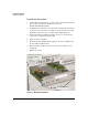
Identifying the Module Interfaces
The HP Advanced Services zl Module has three interfaces.
Internal interface 1 and 2—These two 10 Gigabit Ethernet interfaces
connect to the HP zl switch backplane and provide the LAN connection
for the XenServer that runs on the module. You cannot see these interfaces
on the module’s front panel (they are internal to the module), but the HP
zl switch manages the interfaces just like other switch ports.
These switch ports are <slot-ID> 1 and <slot-ID> 2. So, for example, in a
XenServer Host Module in zl switch slot C, these ports would be C1 and
C2, and they would be untagged members of VLAN 1, by default.
Front Panel Port—This RJ-45 (10/100/1000 Ethernet) interface is on the
module’s front panel. It connects directly to the module and the XenServer
that runs on it rather than to the switch backplane. It must be manually
connected to a switch to be used for communications.
The HP zl switch does not manage this port, and, by default, traffic
received on this interface does not pass through the module and out its
other interfaces.
Using the Switch CLI to Manage the XenServer
The switch command line interface (CLI) can be used to manage the module
and to provide status information on the module hardware. It also provides
access, through an internal serial connection, to the XenServer host CLI or a
management console, for configuring the XenServer host.
You can establish settings for the internal interfaces from the HP zl switch side
and from the module/server side. The settings must be consistent. For exam-
ple, the interface is only accessible if enabled on the switch and on the server.
In addition, if you configure 802.1Q VLAN tags on the server interface, you
must do so on the corresponding switch interface.
On the other hand, you can only control the management interface through
the module or the server that runs on it.
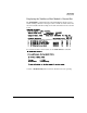
The HP zl switch knows about the module’s internal interfaces and treats them
much like Ethernet interfaces on other zl module interfaces. In the switch CLI,
the interface IDs are <slot>1 and <slot>2. For example, if you have installed
your module in slot C, you can use the
C1 and C2 interface IDs to enable and
di
sable the internal ports and to assign untagged a
nd tagged VLANs to these
interfaces.