HP Advanced Services zl Module with Microsoft® Windows Server® 2008 R2 Installation and Getting Started Guide
© Copyright 2011 Hewlett-Packard Development Company, L.P. The information contained herein is subject to change without notice. All Rights Reserved. This document contains proprietary information, which is protected by copyright. No part of this document may be photocopied, reproduced, or translated into another language without the prior written consent of HewlettPackard.
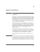
Contents 1 Hardware Installation Overview . . . . . . . . . . . . . . . . . . . . . . . . . . . . . . . . . . . . . . . . . . . . . . . . . . . . . . 1-1 Module Hardware . . . . . . . . . . . . . . . . . . . . . . . . . . . . . . . . . . . . . . . . . . . . 1-2 Module Operating Systems (OSs) . . . . . . . . . . . . . . . . . . . . . . . . . . . . . . . . 1-3 Update the Switch Software . . . . . . . . . . . . . . . . . . . . . . . . . . . . . . . . . . . . . . . 1-4 Set the HP zl Switch Time . . . . . . . .
Server Manager . . . . . . . . . . . . . . . . . . . . . . . . . . . . . . . . . . . . . . . . . . 3-3 Event Viewer . . . . . . . . . . . . . . . . . . . . . . . . . . . . . . . . . . . . . . . . . . . . 3-4 Log Messages . . . . . . . . . . . . . . . . . . . . . . . . . . . . . . . . . . . . . . . . . . . . 3-5 Back Up and Restore . . . . . . . . . . . . . . . . . . . . . . . . . . . . . . . . . . . . . . 3-5 Drive Partitions . . . . . . . . . . . . . . . . . . . . . . . . . . . . . . . . . . . . . . . . .
A EMC Regulatory Statements U.S.A. - FCC Class A . . . . . . . . . . . . . . . . . . . . . . . . . . . . . . . . . . . . . . . . A-1 Canada . . . . . . . . . . . . . . . . . . . . . . . . . . . . . . . . . . . . . . . . . . . . . . . . . . . . A-1 Australia/New Zealand . . . . . . . . . . . . . . . . . . . . . . . . . . . . . . . . . . . . . . . A-1 Japan - VCCI Class A . . . . . . . . . . . . . . . . . . . . . . . . . . . . . . . . . . . . . . . . A-2 Korea . . . . . . . . . . . . . . . . . . . . . . . . .
List Options for a Command . . . . . . . . . . . . . . . . . . . . . . . . . . . . . . . E-6 Command Completion . . . . . . . . . . . . . . . . . . . . . . . . . . . . . . . . . . . . E-6 Displaying Help for a Command . . . . . . . . . . . . . . . . . . . . . . . . . . . . E-6 Operator Context Commands . . . . . . . . . . . . . . . . . . . . . . . . . . . . . . . . . . . . E-7 Index and Name . . . . . . . . . . . . . . . . . . . . . . . . . . . . . . . . . . . . . . . . . . . . . E-7 exit . . . . . . . . .
page . . . . . . . . . . . . . . . . . . . . . . . . . . . . . . . . . . . . . . . . . . . . . . . . . . . . . E-18 ping . . . . . . . . . . . . . . . . . . . . . . . . . . . . . . . . . . . . . . . . . . . . . . . . . . . . . E-18 reboot . . . . . . . . . . . . . . . . . . . . . . . . . . . . . . . . . . . . . . . . . . . . . . . . . . . . E-18 reload . . . . . . . . . . . . . . . . . . . . . . . . . . . . . . . . . . . . . . . . . . . . . . . . . . . . E-19 remote-desktop . . . . . . . . . . . . . . . . .
show assigned-mac-address . . . . . . . . . . . . . . . . . . . . . . . . . . . . . . . . . . . E-27 show chassis . . . . . . . . . . . . . . . . . . . . . . . . . . . . . . . . . . . . . . . . . . . . . . E-28 show logging . . . . . . . . . . . . . . . . . . . . . . . . . . . . . . . . . . . . . . . . . . . . . . E-28 show temperature . . . . . . . . . . . . . . . . . . . . . . . . . . . . . . . . . . . . . . . . . . . E-28 show version . . . . . . . . . . . . . . . . . . . . . . . . . . . . . . . . . . .
1 Hardware Installation Overview The HP Advanced Services zl Module with Microsoft® Windows Server® 2008 R2 (J9666A) is a zl switch module with integrated Windows Server 2008 R2, Standard Edition, software. The module has a 250GB hard disk drive (HDD) and 4GB of DDR3 memory. The server software on the HDD is prelicensed. You install the Advanced Services Module with Microsoft Windows Server 2008 R2 in an HP E5400 zl or E8200 zl Series switch. The module automatically boots to the Windows Server 2008 R2 OS.
Hardware Installation Overview If you want to start immediately, move to “Update the Switch Software” on page 1-4. You can obtain more details about the module in “Module Hardware” on page 1-2 and “Module Operating Systems (OSs)” on page 1-3. Table 1-1.
Hardware Installation Overview c2). These ports carry network traffic to and from the module. The 2 port also carries communications for the Services Management Agent (SMA), which helps the switch to maintain the module and discover information about it. Caution By default, the 1 port 1 is disabled and the 2 port is enabled. You must never disable the 2 port, or the module will fail. The module relies on the switch for its power, clock, and network connectivity.
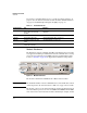
Hardware Installation Update the Switch Software Hard DISK (HD) Integrated AppSW Compact Flash (CF) Service OS Figure 1-2. Module Operating System and Application Update the Switch Software If you need to install the HP zl switch that will house your module, refer to the Installation and Getting Started Guide shipped with the switch or at www.hp.com/networking/support. Before installing the module, you must update the HP zl switch software to version K.14.65 or later. K.15.
Hardware Installation Update the Switch Software ii. Enter this command from the HP zl switch CLI: hostzlswitch# copy usb flash secondary iii. When prompted, press [y]. • TFTP server—Follow these steps: i. Copy the file to a TFTP server that has network connectivity to the HP zl switch. ii. Enter this command from the HP zl switch CLI: hostzlswitch# copy tftp flash secondary iii. When prompted, press [y].
Hardware Installation Update the Switch Software If you do not know the name of the config file that you are using, you can use the help function to see the names of files on your system: hostzlswitch# startup-default secondary config ? 5. Reboot the HP zl switch to the secondary software: hostzlswitch# boot system flash secondary 6. When prompted to reboot the switch, press [y]. 7. When prompted to save the configuration, press [y] again. 8.
Hardware Installation Set the HP zl Switch Time Set the HP zl Switch Time The module gets the current time from the HP zl switch in which it is installed. Important Typically, you will want the server running on the module to participate in a domain. Because the domain join and other functions will fail unless the module’s time matches the domain controller's, the HP zl switch must be set with the correct time.
Hardware Installation Set the HP zl Switch Time The switch calculates the time zone offset in minutes. For example, to specify GMT +1, type 60. 6. When you use RDP to access the Windows Server 2008 R2 that is running on the module, you can access its date and time settings through the Control Panel and activate Daylight Saving Time.
Hardware Installation Set the HP zl Switch Time Replace with the two-digit hour in the 24-hour clock, two-digit minute, and two digit seconds. For example, 10:09:35. 4. Set the timezone: Syntax: time timezone <-780 - 840> The switch calculates the time zone offset in minutes. For example, to specify GMT +1, type 60. 5.
Hardware Installation Install the Module Install the Module Installation Precautions Static electricity can severely damage the electronic components on the module. When handling and installing the module, follow these procedures to avoid damage from static electricity: • Handle the module by its bulkhead or edges and avoid touching the components and the circuitry on the board.
Hardware Installation Install the Module Installation Procedure 1. Use a Torx T-10 or flat-bladed screwdriver to unscrew the screws in the cover plates over the slot where you will install the module. Store the cover plates for possible future use. 2. Hold the module by its bulkhead, taking care not to touch the metal connectors or components on the board. 3. Open the extractor handles. 4.
Hardware Installation Install the Module Verifying That the Module Is Installed Correctly If you have installed the module in a powered off HP zl switch, power up the switch. After the switch powers up, the module will begin to power up. If you have installed the module in a powered on switch, the module begins to power up immediately. The initial bootup takes several minutes.
Hardware Installation Environmental Specifications Environmental Specifications Table 1-3. Environmental Specifications Temperature Operating* Non-Operating 0°C to 45°C (32°F to 113°F) -10°C to 65°C (-10°F to 149°F) Relative humidity (non-condensing) 15% to 90% at 40°C (104°F) 15% to 90% at 65°C (149°F) Maximum altitude 3.0 km (10,000 ft) 4.6 km (15,000 ft) Table 1-4.
Hardware Installation Environmental Specifications Figure 1-6.
2 Getting Started Introduction At this point, your HP zl switch should be installed, and the HP Advanced Services zl Module with Microsoft Windows® Server 2008® R2 should be installed within it. This section guides you through the next steps that must be completed before you can access the module using Remote Desktop Protocol (RDP). If you want to get started immediately, move to “Obtain IP Connectivity to the Module” on page 2-5.
Getting Started Introduction Important In some circumstances, the SMA cannot enable a virtual interface created on interface 2 by Hyper-V. For this reason, it is recommended that you do not activate Hyper-V on this interface. For further recommendations, see “Guidelines for Using Hyper-V” on page 4-11 of Chapter 4: “Special Guidelines for Using the Advanced Services zl Module with Microsoft Windows Server 2008 R2.” At the factory default settings, the interface 1 is disabled and interface 2 is enabled.
Getting Started Introduction The module CLI (hp-svcs-std context)—You can access a CLI that is specific to the module. When you access the windows context for this CLI, you are configuring the server that is running on the module. (See Appendix E: “Command-Line Reference.”) Therefore, if you enable an interface in this CLI, you are enabling the interface from the server side.
Getting Started Introduction This guide will refer to the interfaces as interface 1, interface 2, and the management interface. Table 2-1.
Getting Started Obtain IP Connectivity to the Module Obtain IP Connectivity to the Module You have two choices for reaching the Windows Server 2008 R2 OS that runs on the module for the first time: You can access the module on its default management IP address, 192.168.2.10/30. See “Access the Module on its Management IP Address” on page 2-5. You can establish a management session with the module’s host zl switch CLI.
Getting Started Obtain IP Connectivity to the Module Set the VLAN and Determine the Module’s IP Address You must now determine the IP address at which to contact the module. (Sometimes the module receives a fixed DHCP address from a reservation, but you should still verify that the proper address has been received.) In order to do this, you must first set the VLAN for the module. Follow these steps: 1. Access the HP zl switch CLI and move to the Global Configuration level. 2.
Getting Started Obtain IP Connectivity to the Module Figure 2-2. HP zl Switch CLI—show services Output 4. Access the module’s application OS: Syntax: services Replace with the ID of the slot in which the module is installed. Replace with the index number that you just noted for the service.
Getting Started Obtain IP Connectivity to the Module 8. When you have verified connectivity, exit the module CLI. hostzlswitch(hp-svcs-std-C)# exit Set an IP Address Follow these steps: 1. You should be in the module CLI (hp-svcs-std context). If necessary, enter this command from the HP zl switch’s Global Configuration level: hostzlswitch(config)# services name hp-svcs-std 2. Log in to the Windows context: hostzlswitch(hp-svcs-std-C)# windows SBMAdmin 3.
Getting Started Obtain IP Connectivity to the Module hostzlswitch(hp-svcs-std-C:eth-2)# ip default-gateway For example: hostzlswitch(hp-svcs-std-C:eth-2)# ip address 10.1.1.50 255.255.255.0 hostzlswitch(hp-svcs-std-C:eth-2)# ip default-gateway 10.1.1.1 If you want, you can also set the DNS server: hostzlswitch(hp-svcs-std-C:eth-2)# ip dns server-address priority [1 |2] For example: hostzlswitch(hp-svcs-std-C:eth-2)# ip dns server-address priority 1 10.2.1.
Getting Started Access the Module using Remote Desktop Protocol (RDP) Access the Module using Remote Desktop Protocol (RDP) As a final step in verifying that the module is installed, connected, and ready to configure, access it using RDP. 1. From your management station’s Start menu, select Programs > Accessories > Remote Desktop Connection. (The path might vary slightly based on your OS and settings.) Figure 2-3. Remote Desktop Connection Window 2.
Getting Started Access the Module using Remote Desktop Protocol (RDP) 3. When your management workstation runs Windows 7, you might see a warning because your station does not trust the module’s self-signed certificate. If you do not want to see this warning again, select the Don’t ask me again for connections to this computer check box. Then click Yes. Figure 2-4. Remote Desktop Connection Error 4. When prompted, log in as Administrator. 5.
Getting Started Access the Module using Remote Desktop Protocol (RDP) Figure 2-5. Module’s Windows Server 2008 R2 Remote Desktop 7. Click Start > Control Panel. 8. Click System and Security and then System. 9. In this window, you can see your module’s computer name (which is its serial number, by default) as well as its current software version. You can also click Online help to be directed to services and tech support resources.
Getting Started Access the Module using Remote Desktop Protocol (RDP) Figure 2-6. System Window Manage the Network Connections You might have already verified or set the module’s IP address through its CLI. However, it is a good idea to access the Network Connections window and make sure that you understand how the Windows Server 2008 R2 Local Area Connection interfaces match up with the module interfaces.
Getting Started Access the Module using Remote Desktop Protocol (RDP) 1. Access the Network Connections window through the Control Panel. Figure 2-7. Network Connections 2. Important You should see three Local Area Connection interfaces. The Windows Server 2008 R2 assigns these interfaces to the module’s three ports when it boots up. You can determine which interface is assigned to which port by examining the IP address, speed, and status: • One interface is a Gigabit interface.
Getting Started Access the Module using Remote Desktop Protocol (RDP) 3. If you have accessed the server running on your module through the module’s management port, you should verify that the server has the correct IP address on your network. Generally, this IP address should be assigned to the Local Area Connection interface that is associated with the 2 internal port. If your company uses DHCP to assign fixed addresses to servers, verify that this interface has received the correct address.
Getting Started Access the Module using Remote Desktop Protocol (RDP) 4. Important 2-16 f. If you want to set the DNS server addresses manually, select Use the following DNS server addresses and specify the addresses. g. Click OK. h. Click Close. If you want, you can change the IP address on the module’s management interface. Again, follow the standard Windows procedure. If you change the IP address of the interface on which you are currently connected, you will lose your RDP session.
3 Management Overview You have several options for monitoring and maintaining the HP Advanced Services zl Module with Microsoft® Windows Server® 2008 R2: Remote Desktop Protocol (RDP) to the module’s Windows Server 2008 R2 OS—Allows you to manage this headless server much as you would any server. See “Remote Desktop Protocol (RDP)” on page 3-2.
Management Remote Desktop Protocol (RDP) Remote Desktop Protocol (RDP) An RDP session provides your primary option for monitoring and managing the module’s Windows Server 2008 R2 OS. As with any server, you can log in as a domain user or a local Administrator, and different tasks will be available to you based on your domain policies. Enable and Disable the Remote Desktop Remote Desktop connections to the module are enabled by default.
Management Remote Desktop Protocol (RDP) 4. Activate the remote desktop: hostzlswitch(hp-svcs-std-C:win)# remote-desktop To disable the remote desktop, enter this command: hostzlswitch(hp-svcs-std-C:win)# no remote-desktop Use the Remote Desktop All typical Windows tools are available from the Remote Desktop. A few of these tools are briefly discussed in the sections below. This information is in no way intended as comprehensive.
Management Remote Desktop Protocol (RDP) Figure 3-2. Remote Desktop—Server Manager Event Viewer Another useful tool is the Event Viewer, which you can access from Start > Administrative Tools > Event Viewer. You can also open the Server Manager and expand Diagnostics. Events related to the module’s functionality are reported under Event Viewer > Applications and Services Logs > HP SMA.
Management Remote Desktop Protocol (RDP) Figure 3-3. Remote Desktop—Server Manager > Diagnostics > Event Viewer Log Messages The server stores a variety of log messages. If the module crashes, you can find the crash dump file in the C:\Windows folder. The file will have a name such as MEMORY.DMP. Back Up and Restore You can back up and restore your system using the Windows Server Backup feature, which is installed on the module at the factory default settings and accessible from the Administrative Tools.
Management Remote Desktop Protocol (RDP) Figure 3-4.
Management Special Administration Console (SAC) Special Administration Console (SAC) The following HP zl switch command gives you pass through access to the command line for the Windows Server 2008 R2 that is running on the module: hostzlswitch(config)# services tech Note that the command must be entered from the switch’s Global Configuration level. If you enter this command while the module is booting, you can monitor the bootup process.
Management Special Administration Console (SAC) Figure 3-5. SAC—help command You can exit the SAC at any time and return to the HP zl switch CLI by pressing [Ctrl][Z]. If you want to access the Windows command prompt, follow these steps: 1. Activate the Windows Server 2008 R2 command prompt: SAC> cmd The command prompt is assigned to a channel, and the channel’s name and number are displayed. Figure 3-6.
Management Special Administration Console (SAC) 2. Access the command prompt channel: SAC> ch -si For example: SAC> ch -si 1 You should see that you are entering the command prompt channel. 3. Press [Spacebar]. 4. When prompted, log in with your domain or local Administrator credentials. 5. You can then enter Windows command line commands. 6. To return to the SAC, type exit. 7. You should see that you are entering the SAC channel. Figure 3-7. SAC—SAC Channel 8.
Management Special Administration Console (SAC) The module automatically boots to the Recovery Menu if it fails to boot the OS. You can also force the module to boot to this menu by accessing the module’s command prompt via RDP, entering reagentc /boottore, and rebooting the module. After the module boots, enter the services tech command from the HP zl switch CLI; you will be placed in the Recovery Menu. From the Recovery Menu, you can enter R to revert the module to its factory image.
Management SNMP MIBs 5. As the module reboots, messages will be displayed. You will see the Safe Mode options. Figure 3-8. Safe Mode Options 6. Use the arrow keys to select an option and press [Enter] to confirm. These options remain for 30 seconds. If you do nothing, the module boots normally. After the module boots up, you will see the SAC prompt.
Management SNMP MIBs Microsoft might offer updates for these MIBs; refer to Microsoft for more information. Intel NIC MIBs The current version for these MIBs in 15.5 (14.7 or later is supported). You can obtain these MIBs (as well as updates for MIBs should the Intel driver be updated) from Intel’s Web site. Look for and download the Ethernet Connections CD; the MIBs are typically contained in the APPS\SNMP\MIB folder of that download.
4 Special Guidelines for Using the Advanced Services zl Module with Microsoft Windows Server 2008 R2 Overview In almost every way, the HP Advanced Services Module with Microsoft® Windows Server® 2008 R2 functions like any other server. However, you do need to keep a few guidelines in mind.
Special Guidelines for Using the Advanced Services zl Module with Microsoft Windows Server 2008 R2 Network Monitoring Applications Network Monitoring Applications The module’s HP Services Management Agent (SMA) uses WinPcap for certain necessary communications with the switch. These communications allow you to access the module CLI. They also report the module status to the switch, and verify the module’s software integrity and licensing. It is very important that you do not disrupt the SMA’s operations.
Special Guidelines for Using the Advanced Services zl Module with Microsoft Windows Server 2008 R2 Network Monitoring Applications 2. Install the application. When you reach the WinPcap installation, you might see an error such as the one shown in Figure 4-1. You can ignore this error. Figure 4-1. WinPcap Installation Error 3. After the application has installed, you must reconfigure the SMA so that it recognizes the new WinPcap file.
Special Guidelines for Using the Advanced Services zl Module with Microsoft Windows Server 2008 R2 Restoring the Module to the Factory Image Uninstalling Applications with WinPcap If you need to uninstall a program that uses WinPcap, you should leave WinPcap on the system if possible. Many uninstall wizards allow you to choose which components you wish to install. Figure 4-2 shows the Uninstall screen for Wireshark.
Special Guidelines for Using the Advanced Services zl Module with Microsoft Windows Server 2008 R2 Restoring the Module to the Factory Image restore the module. Make sure that you have the appropriate updates available before you begin the factory reset process. Also make sure to archive any information that you do not want to lose. Based on the roles fulfilled by your module, the domain administrator might need to complete some tasks.
Special Guidelines for Using the Advanced Services zl Module with Microsoft Windows Server 2008 R2 Restoring the Module to the Factory Image 4. Wait a few moments. The module will then shutdown. The next steps depend on how you accessed the command prompt: • From the SAC—You will be returned to the SAC and warned that the system is about to shut down. Wait. As the module reboots, messages will be displayed. • Via RDP—You will lose your RDP connection. Follow these steps: i.
Special Guidelines for Using the Advanced Services zl Module with Microsoft Windows Server 2008 R2 Default Policies That Must Not Be Changed 7. The restoration takes about twenty minutes. You can exit the Recovery Menu at any time by pressing [Ctrl][Z]. After the module has rebooted, you can contact it and manage it as a new module. Refer to Chapter 2: “Getting Started.” Remember also to reapply any updates or patches.
Special Guidelines for Using the Advanced Services zl Module with Microsoft Windows Server 2008 R2 Default Policies That Must Not Be Changed Table 4-1 displays the USGCB recommended settings that must not be implemented. The correct setting is configured by default unless a domain policy changes it when the module joins the domain. Therefore, you should check your domain policies for the settings shown in the table, and disable those policies for the module.
Special Guidelines for Using the Advanced Services zl Module with Microsoft Windows Server 2008 R2 Security Hardening at the Factory Default Settings Table 4-2. Settings that Might Cause Issues Setting’s Registry Path or Policy Path Windows 7 USGCB Recommended Setting Possible Issue Policy Path: Profile system performance = Administrators,NT SERVICE\WdiService Host A known Windows issue causes the WdiServiceHost to be written incorrectly. Refer to: http:// support.microsoft.co m/kb/2000705.
Special Guidelines for Using the Advanced Services zl Module with Microsoft Windows Server 2008 R2 Security Hardening at the Factory Default Settings Table 4-3. Windows 7 USGCB Recommended Settings Implemented at Factory Default Settings Setting’s Registry Path or Policy Path Implemented USGCB Setting HKCU\Software\Policies\Microsoft\Windows\Control Panel\Desktop!ScreenSaveActive; should be in HKU\.
Special Guidelines for Using the Advanced Services zl Module with Microsoft Windows Server 2008 R2 Guidelines for Using Hyper-V Setting’s Registry Path or Policy Path Implemented USGCB Setting Policy path (no registry setting): Enforce password history = 24 passwords remembered Computer Configuration\Windows Settings\Security Settings\Account Policies\Password Policy Maximum password age = 60 days Minimum password length = 12 characters Policy path (no registry setting): Computer Configuration\Windows
Special Guidelines for Using the Advanced Services zl Module with Microsoft Windows Server 2008 R2 Guidelines for Using Hyper-V ating system environment (VOSE). If you choose to use the VOSE, the POSE can do nothing but support the VOSE. (In this case, the POSE is sometimes referred to as the Host OS, and the VOSE, as the Guest OS.) Note When you activate Hyper-V, you must tap the shutdown button on the module twice to shut down the module.
Special Guidelines for Using the Advanced Services zl Module with Microsoft Windows Server 2008 R2 Guidelines for Using Hyper-V When you activate Hyper-V on an interface, Hyper-V disables all services associated with the physical interface except the Microsoft Virtual Switch Protocol and creates a virtual adapter bridged to this interface. The new virtual interface is now associated with the IP address. If you open the Network Connections window, you will see the new interface listed.
Special Guidelines for Using the Advanced Services zl Module with Microsoft Windows Server 2008 R2 Guidelines for Using Hyper-V Figure 4-4. Windows Server Manager > Roles > Hyper-V > Hyper-V Manager 4-14 5. In the Actions pane, click Virtual Network Manager. 6. In the right pane, select the virtual interface. 7. Leave the Connection Type as External, but clear the Allow managing operating system to share this network adapter check box.
Special Guidelines for Using the Advanced Services zl Module with Microsoft Windows Server 2008 R2 Guidelines for Using Hyper-V Figure 4-5. Windows Virtual Network Manager 8. Important Click OK. You can lose management access to the module if you have not followed the recommendations. Make sure that: ■ You have activated Hyper-V on interface 1. ■ You have not activated Hyper-V on interface 2. ■ Interface 2 has an IP address.
Special Guidelines for Using the Advanced Services zl Module with Microsoft Windows Server 2008 R2 Guidelines for Using Hyper-V 4-16
5 Troubleshooting View Crash Dump Files using the SAC If the module crashes, you can find the crash dump file in C:\Windows\MEMORY.dmp. If you can access the OS using RDP, simply navigate to the file. If you cannot reach the OS using RDP, you can reach it using the SAC. Follow these steps: 1. Access the CLI for the HP zl switch chassis in which the module is installed. 2. Move to global configuration mode: hostzlswitch# config 3.
Troubleshooting View Crash Dump Files using the SAC Figure 5-1. SAC—CMD Prompt Channel 7. Access the command prompt: SAC> ch -si For example: SAC> ch -si 1 8. You should see that you are entering the command prompt channel. Press [Spacebar]. 9. Note When prompted, enter your local Administrator username and password. Press [Enter] for Domain. If you have not yet changed the username and password, the defaults are SBMAdmin and P@ssw0rd.
Troubleshooting View Crash Dump Files using the SAC 11. Return to the SAC: a. Press [Esc] + [Tab] + [0]. b. You should see that you are entering the SAC channel. Figure 5-2. SAC—SAC Channel c. Press [Spacebar]. 12. Press [Ctrl][Z] to access the HP zl switch CLI.
Troubleshooting Gain Access to a Module that Has No Network Connectivity Gain Access to a Module that Has No Network Connectivity Read this section if you cannot gain access to the headless server that is running on your module. Note You will find it easier to troubleshoot if you understand the differences between the module’s three interfaces and how your server is using them. Refer to “Module Interfaces” on page 2-1 in Chapter 2: “Getting Started.
Troubleshooting Gain Access to a Module that Has No Network Connectivity With your new RDP session, you can look for problems that caused the server to lose network connectivity. For example, look for disabled interfaces. Note that, if Hyper-V is activated on an interface, both the physical interface associated with the NIC and the virtual interface associated with the IP address must be enabled.
Troubleshooting Gain Access to a Module that Has No Network Connectivity You might also check the HP zl switch configuration for issues: The module interface through which you access the server running on the module is disabled. Note that, if the module’s interface 2 is disabled, you cannot access the module CLI. You should enable the interface immediately.
Troubleshooting Gain Access to a Module that Has No Network Connectivity 3. Enter this command: Syntax: services tech Replace with the ID for the slot in which the module is installed. For example: hostzlswitch(config)# services c tech 4. Press [Enter] until you see this prompt: SAC> 5. You are in the Special Administration Console (SAC). 6. Activate the Windows Server 2008 R2 command prompt: SAC> cmd Figure 5-3. SAC—CMD Prompt Channel 7.
Troubleshooting Gain Access to a Module that Has No Network Connectivity disabled interfaces. Note that, if Hyper-V is activated on an interface, both the physical interface associated with the NIC and the virtual interface associated with the IP address must be enabled. You might also look for issues with your Windows firewall and with 802.1Q tagging if your server interface is using that protocol. 8. If you are unable to establish an RDP session, you must continue to use the SAC to resolve the problem.
Troubleshooting Gain Access to a Module that Has No Network Connectivity ipconfig/all b. Enter this command to enable the interface: netsh interface set interface ENABLED You should then be able to regain access to the module. Module’s Behavior Based on Enabled and Disabled Interfaces Table 5-1 indicates how the module behaves based on the status of its interfaces.
Troubleshooting Gain Access to a Module that Has No Network Connectivity 10 Enabled Disabled Disabled C, E Yes, but quickly and automatically reverts to 6 11 Disabled Enabled Disabled C, E Yes, but quickly and automatically reverts to 7 12 Disabled Disabled Disabled C, E Yes, but quickly and automatically reverts to 8 Yes 13 Enabled Enabled Enabled A, B 14 Enabled Enabled Disabled A, D, G No.
Troubleshooting Restore a Module Reported as Failed Result: A = Interface 1 is up and functioning normally B = Interface 2 is up and functioning normally C = Interface 1 is down and unavailable D = Interface 2 is down and unavailable. The SMA and the module CLI are still available. E = The CLI is down for less than 30 seconds. Then the SMA brings interface 2 back up (if Hyper-V is in use, the SMA brings the physical interface 2 back up). F = The SMA brings the virtual interface 2 back up.
Troubleshooting Restore a Module Reported as Failed Recover from a Disabled Port 2 If someone has disabled the module’s internal port 2 from the host zl switch CLI, the module will fault and you will not be able to access the module CLI. Follow these steps to recover the module: 1. Access the host zl switch CLI. 2.
Troubleshooting Restore a Module Reported as Failed b. You must save the file with a .reg extension. Double-check that the file type is Registration Entry and not Text Document. c. Double-click the file to execute the registration change. d. Accept any prompts. e. When you see The keys and values …have been successfully added to the registry message, restart the module. After the reboots, the management connection should be restored and the module should function correctly.
Troubleshooting Restore a Module Reported as Failed 5-14
EMC Regulatory Statements A EMC Regulatory Statements U.S.A. - FCC Class A This equipment has been tested and found to comply with the limits for a Class A digital device, pursuant to Part 15 of the FCC Rules. These limits are designed to provide reasonable protection against interference when the equipment is used in a commercial environment.
EMC Regulatory Statements Japan - VCCI Class A Korea Taiwan European Community Declaration of Conformity This product is designed for operation with the HP ProCurve switches that have zl module slots. Refer to the Declarations of Conformity included in the Installation Guides for those products.
Waste Electrical and Electronic Equipment (WEEE) Statements B Waste Electrical and Electronic Equipment (WEEE) Statements Disposal of Waste Equipment by Users in Private Household in the European Union This symbol on the product or on its packaging indicates that this product must not be disposed of with your other household waste.
Waste Electrical and Electronic Equipment (WEEE) Statements Laitteiden hävittäminen kotitalouksissa Euroopan unionin alueella Jos tuotteessa tai sen pakkauksessa on tämä merkki, tuotetta ei saa hävittää kotitalousjätteiden mukana. Tällöin hävitettävä laite on toimitettava sähkölaitteiden ja elektronisten laitteiden kierrätyspisteeseen.
Waste Electrical and Electronic Equipment (WEEE) Statements Smaltimento delle apparecchiature da parte di privati nel territorio dell'Unione Europea Questo simbolo presente sul prodotto o sulla sua confezione indica che il prodotto non può essere smaltito insieme ai rifiuti domestici. È responsabilità dell'utente smaltire le apparecchiature consegnandole presso un punto di raccolta designato al riciclo e allo smaltimento di apparecchiature elettriche ed elettroniche.
Waste Electrical and Electronic Equipment (WEEE) Statements Descarte de Lixo Elétrico na Comunidade Européia Este símbolo encontrado no produto ou na embalagem indica que o produto não deve ser descartado no lixo doméstico comum. É responsabilidade do cliente descartar o material usado (lixo elétrico), encaminhando-o para um ponto de coleta para reciclagem.
Hardware Components Front Panel Buttons, LEDs, and Connectors C Hardware Components Front Panel Buttons, LEDs, and Connectors This section describes the different buttons, LEDs, and connectors on the front panel of a module: ■ Caution Module Shutdown button—This button is used to shut down the module. A message is written to the switch log to indicate the module has shut down.
Hardware Components Front Panel Buttons, LEDs, and Connectors ■ USB Port—This port is used to attach a USB device, such as a flash drive. The USB device is then available on the headless server. Table C-1. Module LEDs Module LED State Module Statusa (green/ orange) Meaning When the module is first installed, this LED follows the following sequence: 1. Green for ~15s - The module has power. 2. Orange for ~11s - Testing the LED. 3. Green for ~4s - Starting self-test. 4.
Hardware Components Internal Ports Internal Ports The module receives traffic from and transmits traffic to its host switch on two internal Ethernet ports, each of which supports 10 Gbps. When a module is installed into the host switch, the switch automatically detects these internal ports and names them according to the slot in which the module is installed. For example, if the module is installed in slot A, the switch references the ports as A1 and A2.
Hardware Components Serial Numbers Disk drive serial and product numbers Figure C-1. Locating the disk drive serial number The serial number for the module is located on the back left corner of the module (Figure C-2). Module serial number SN: SGxxxxxxxx Figure C-2.
Hardware Components Switch LEDs Switch LEDs The following figures show the Test, Fault, and Module Status LEDs on the switches the module can be installed in. Test LED Fault LED Module Status LEDs Figure C-3. Test, Fault, and Module Status LEDs on an E5400 zl Series switch Fault LED Test LED Module Status LEDs Figure C-4.
Hardware Components Replacing or Removing a Module Replacing or Removing a Module It is highly recommended that the module be shutdown before replacing or removing it.
Hardware Components Replacing Field Replaceable Units (FRUs) Caution For proper cooling and reduction of electromagnetic emissions, ensure that a slot cover is installed on any unused slot. In an operational chassis, an unused slot should be covered if it is not used for more than 2 minutes.
Hardware Components Replacing Field Replaceable Units (FRUs) C-8
Software Components Updating Switch Software D Software Components Updating Switch Software The HP Advanced Services zl Module with Microsoft® Windows Server® requires switch software version K.14.65 or later to be installed in the switch. Version K.15.03 or greater is recommended if the module is installed in an HP E8200 zl switch with dual management modules. K.15.03 will gracefully shutdown and restart the module in the event of a management module failover. (Version K.14.
Software Components Updating Switch Software There are some conditions when Ctrl-C may not work; in these cases, use Ctrl-Z.
Software Components Updating the Service OS Updating the Service OS There are two ways to update the Service OS: Note ■ via FTP: used when a local FTP server is accessible from the module ■ via USB: used when a local FTP server is not accessible from the module The process of updating the Service OS is faster if the switch is accessed via Telnet or SSH; the serial console slows down the writing of characters to the screen, causing a significantly slower installation speed, especially if the switch co
Software Components Updating the Service OS hostswitch(svcs-mod-C:SvcOS)# boot ServiceOS Changing boot from CF Service OS to Service OS. System will be rebooted. Do you want to continue [y/n]? y Rebooting 7. Check the version of the updated Service OS and confirm it is running: hostswitch(svcs-mod-C:SvcOS)# show version Updating Service OS via USB Note Any image folder (Service or application) can be put on a USB flash drive and transferred to the Service image repository. 1.
Software Components Device Disable Device Disable The module offers improved security and reliability. In case there is no physical security on the chassis, the USB and the shutdown button can be disabled to prevent unauthorized or undesired access. Both the USB and the shutdown button are enabled by default. The USB is disabled during boot. Use the “device” command without an argument to show the devices enabled/ disabled.
Software Components Device Disable D-6
E Command-Line Reference Contents Overview . . . . . . . . . . . . . . . . . . . . . . . . . . . . . . . . . . . . . . . . . . . . . . . . . . . . . . E-4 Command Syntax Statements . . . . . . . . . . . . . . . . . . . . . . . . . . . . . . . . . E-5 CLI Help . . . . . . . . . . . . . . . . . . . . . . . . . . . . . . . . . . . . . . . . . . . . . . . . . . . E-5 List Available Commands . . . . . . . . . . . . . . . . . . . . . . . . . . . . . . . . . E-6 List Options for a Command . . . . . . . . . . . . .
Command-Line Reference Contents show ip . . . . . . . . . . . . . . . . . . . . . . . . . . . . . . . . . . . . . . . . . . . . . . . . . . . E-15 show remote-desktop . . . . . . . . . . . . . . . . . . . . . . . . . . . . . . . . . . . . . . . E-15 show tech . . . . . . . . . . . . . . . . . . . . . . . . . . . . . . . . . . . . . . . . . . . . . . . . . E-15 show version . . . . . . . . . . . . . . . . . . . . . . . . . . . . . . . . . . . . . . . . . . . . . . E-15 shutdown . . . . . . . . . . . . . . .
Command-Line Reference Contents reload . . . . . . . . . . . . . . . . . . . . . . . . . . . . . . . . . . . . . . . . . . . . . . . . . . . . E-23 show firewall . . . . . . . . . . . . . . . . . . . . . . . . . . . . . . . . . . . . . . . . . . . . . . E-24 show interfaces . . . . . . . . . . . . . . . . . . . . . . . . . . . . . . . . . . . . . . . . . . . . E-24 show ip . . . . . . . . . . . . . . . . . . . . . . . . . . . . . . . . . . . . . . . . . . . . . . . . . . . E-24 show remote-desktop . . . .
Command-Line Reference Overview Overview This chapter describes the commands provided by the command line interface (CLI) for the HP Advanced Services zl Module with Microsoft® Windows Server 2008® R2. This CLI is intended for basic monitoring and initial IP configuration. Most management and configuration should be performed using the Remote Desktop as described in previous chapters of the guide. The CLI is context-based; different commands are available from different contexts.
Command-Line Reference Overview Table E-2.
Command-Line Reference Overview List Available Commands The CLI help provides several ways to display the options available in a particular context.: ■ ? ■ Tab key For example, to view the commands available at the module’s manager context, you could type one of the following: hostzlswitch(hp-svcs-std-)# ? or hostzlswitch(hp-svcs-std-)# [tab] A list of commands available in the manager context would be displayed.
Command-Line Reference Operator Context Commands Operator Context Commands The Operator context features a limited number of commands that allow you to see information about the module. To access the Operator context, access the operator context of the CLI of the HP zl switch in which the module is installed. Then enter the following command: Syntax: services < | name hp-svcs-std > Moves you to an OS context on the module.
Command-Line Reference Operator Context Commands To view the index numbers, names, and their associated chassis slots, enter the following command from the HP zl switch’s CLI: hostzlswitch> show services Table E-3 shows an example output for this command. In this example, the host HP zl switch has assigned the module the index number 2. Table E-3. CLI Display of Services Slot Index Description Name C 1. Services zl Module services-module C 2.
Command-Line Reference Operator Context Commands The following sections describe commands that are available from the Operator context of the module’s ONE-App OS. exit The exit command moves you back one context level. In the manager EXEC context level, this command returns you to the HP zl switch CLI. Syntax: exit This command is available from all contexts. page This command enables and disables page mode.
Command-Line Reference Operator Context Commands show ip This command shows IP information for the three module interfaces: ■ Internal Ethernet Port 1 ■ Internal Ethernet Port 2 ■ Management Port The IP information includes the interface’s DHCP setting and status, as well as the interface’s IP address, subnet mask, default gateway, gateway metric, DNS servers, and WINS servers. The command also outputs the module’s hostname. Note The Management port is not functional for beta implementations.
Command-Line Reference Manager EXEC Context Commands show version This command displays the version of the module’s ONE-App software. This will include a version identifier for the HP software and the media gateway version. Syntax: show version This command is available from all contexts. Manager EXEC Context Commands The Manager EXEC context features a limited number of commands that allow you to see information about the module or to restart or shutdown the module.
Command-Line Reference Manager EXEC Context Commands If there are no other types of ONE Services zl Modules installed in the switch, the host switch assigns the module the index number 2. If other types of ONE Services zl Modules are also installed in the switch, the host switch assigns the module and each ONE Services zl product a different index number, based on the order in which each one boots.
Command-Line Reference Manager EXEC Context Commands Table E-6. CLI Display of Services Slot Index Description Name C,D 1. Services zl Module services-module D 2. Data Center Connection Manager dcm C 3. Branch Core Svcs-Standard hp-svcs-std For example, if you want to enter the Manager EXEC context for the module’s ONE App OS, enter one of the following commands: hostzlswitch# services c 3 hostzlswitch# services c name hp-svcs-std To verify your location in the CLI, check the prompt.
Command-Line Reference Manager EXEC Context Commands This command is available from all contexts. Syntax: [no] page ping This command sends an ICMP echo packet to the specified IP address. You can use it to test IP connectivity. Syntax: ping reboot This command powers down the module and reboots it. Syntax: reboot reload This command reloads the module. Syntax: reload show firewall This command displays the status of the Windows firewall, whether on or off.
Command-Line Reference Manager EXEC Context Commands show ip This command shows IP information for the three module interfaces: ■ Internal Ethernet Port 1 ■ Internal Ethernet Port 2 ■ Management Port The IP information includes the interface’s DHCP setting and status, as well as the interface’s IP address, subnet mask, default gateway, gateway metric, DNS servers, and WINS servers. The command also outputs the module’s hostname. Syntax: show ip This command is available from all contexts.
Command-Line Reference Manager EXEC Context Commands Syntax: show version This command is available from all contexts. shutdown This command shuts down the module gracefully. You will be exited to the host HP zl switch CLI. (To restart the module, you can enter services reload.) Syntax: shutdown windows This commands moves you to the Windows administration context, which enables you to modify a few settings on the Windows system.
Command-Line Reference Windows Administration Context Windows Administration Context From the Windows administration context, you can make configurations to set up the module to be accessed in other ways. The same commands available from the Manager EXEC mode are also available. The following sections describe commands available from the Windows administration context. end To return to the manager context, enter end.
Command-Line Reference Windows Administration Context interface This command moves you to an interface configuration context. Syntax: interface <1 | 2 | management> Type 1 to configure the Internal Ethernet Port 1 (corresponds with the 1 port in the HP zl switch CLI). Type 2 to configure the Internal Ethernet Port 2 (corresponds with the 2 port in the HP zl switch CLI). Type management to configure the Management port on the front panel of the module.
Command-Line Reference Windows Administration Context reload This command reloads the module. Syntax: reload remote-desktop Enables or disables (no) access to the module via Remote Desktop Protocol (RDP). Syntax: [no] remote-desktop show firewall This command displays the status of the Windows firewall, whether on or off. Syntax: show firewall This command is available from all contexts.
Command-Line Reference Windows Administration Context The IP information includes the interface’s DHCP setting and status, as well as the interface’s IP address, subnet mask, default gateway, gateway metric, DNS servers, and WINS servers. The command also outputs the module’s hostname. Syntax: show ip This command is available from all contexts. show remote-desktop This command displays the status of the Remote Desktop, whether enabled or disabled.
Command-Line Reference Interface Configuration Mode shutdown This command shuts down the module gracefully. You will be exited to the host HP zl switch CLI. (To restart the module, you can enter services reload.) Syntax: shutdown Interface Configuration Mode This section describes the commands that are available from the interface configuration mode.
Command-Line Reference Interface Configuration Mode ip default-gateway This command sets the default gateway for an interface with a static IP address. Syntax: ip default-gateway [metric] Replace with the IP address of the router or routing switch on this interface’s subnet. You can optionally specify a value for the metric. The lower the metric, the higher the priority of the default route on this interface.
Command-Line Reference Interface Configuration Mode end To return to the manager context, enter end. The end command moves you back to the manager context, regardless of the context from which you enter the command. Syntax: end This command is available from all contexts. exit The exit command moves you back one context level. Here, it returns you to the Windows administration context. Syntax: exit This command is available from all contexts. page This command enables and disables page mode.
Command-Line Reference Interface Configuration Mode show firewall This command displays the status of the Windows firewall, whether on or off. Syntax: show firewall This command is available from all contexts. show interfaces This commands shows the three module interfaces and whether they are enabled or not: ■ Internal Ethernet Port 1 ■ Internal Ethernet Port 2 ■ Management port Syntax: show interfaces This command is available from all contexts.
Command-Line Reference Interface Configuration Mode show remote-desktop This command displays the status of the Remote Desktop, whether enabled or disabled. When enabled, you can access the module via Remote Desktop Protocol (RDP) and manage the device much like any Windows Server 2008 R2. Syntax: show remote-desktop This command is available from all contexts. show tech This command outputs all available system information, including the running configuration and logs.
Command-Line Reference Services OS Operator Context Commands Services OS Operator Context Commands The Services OS operator context allows restricted access to some troubleshooting commands on the Services OS of the module. To access this context, enter the following command from the host switch’s operator-level context: Syntax: services < 1 | name svcs-mod > Moves you to an OS context on the module. Replace with the letter for the lower chassis slot in which the module is installed.
Command-Line Reference Services OS Operator Context Commands exit The exit command moves you back to the host HP zl switch CLI. Syntax: exit This command is available from all contexts. page This command enables and disables page mode. In page mode, the terminal output will pause when it fills the screen and wait for a keystroke such as space or [Ctrl][C]. Syntax: [no] page ping Use this command to send an ICMP echo to a specified destination.
Command-Line Reference Services OS Operator Context Commands show chassis This command shows the chassis slot in which the module resides. Syntax: show chassis show logging This command shows all of the logging information. You can view the following locally logged events. To view the locally logged events, enter the following command: Syntax: show logging [-a] [-r] [-d] [option string] The log will be displayed with the most recent last, unless you specify otherwise.
Command-Line Reference Services OS Manager Context Commands Services OS Manager Context Commands The Services OS manager context allows restricted access to the Services OS of the module, providing only a limited number of commands. From this mode, you can download and install software. CLI access to the Services OS is designed primarily for blade maintenance, not for configuring the module. The Services OS context is used to complete basic setup and maintenance tasks.
Command-Line Reference Services OS Manager Context Commands The sections below describe commands that you can use to view settings and boot to the ONE-app software. The Services OS also provides the following commands, which you must not use unless so directed by an HP networking support agent: ■ delete ■ download ■ install ■ sdk ■ sync ■ uninstall ■ update ■ usb boot This command allows you to boot the module’s different operating systems. You can boot the Services OS or the ONE-App OS.
Command-Line Reference Services OS Manager Context Commands exit The exit command moves you back to the host HP zl switch CLI. Syntax: exit This command is available from all contexts. ip This is the only configuration command available from the Services OS manager context. It allows you to configure an IP address and default gateway on the Services OS so that the module can communicate with an FTP server.
Command-Line Reference Services OS Manager Context Commands For example: hostzlswitch(services-module-)> ping 10.1.1.1 When you send ICMP echoes, the module displays the ping statistics to describe the types of responses the router receives. show assigned-mac-address This command shows the MAC addresses assigned to the module’s two internal ports by the HP zl switch.
Command-Line Reference Services OS Manager Context Commands The log will be displayed with the most recent last, unless you specify otherwise. An explanation of the optional choices is listed below: ■ -a—show all log events (including events from previous boot cycles) ■ -r—show log events in reverse order (most recent first) ■ -d—show all log events of debug level or higher ■ option string—filters the log events show temperature This command shows the temperature of the blade in degrees Celsius.
Command-Line Reference Services OS Manager Context Commands E-34
Index B backup and restore … 3-5 IP address management … 2-5 set … 2-8 view from BoB CLI … 2-6 C CLI Command boot ONE-app … D-4 shutdown … C-1, C-6 CLI commands … E-1 Command Line Interface (CLI) … 1-1 show version … D-1 Switch … C-2, D-1 Compact Flash … 1-3 L LED Behavior … 1-2, 1-12, 5-9 Fault … 1-12 HDD Activity … C-2 Meaning … C-2 Module Locator … C-2 Module Status … 1-12, C-2 Network Activity … C-2 State … C-2 Switch … C-5 Test … 1-12 D Device Disable … D-5 DNS server set … 2-9 M E failed managem
disable … 3-2 enable … 3-2 overview … 3-2 use … 3-3 Replacing the Disk Drive … C-7 S SAC … 3-7 safe mode … 3-10 security hardening default settings … 4-9 Serial Numbers … C-3 Service OS … D-4 Services Management Agent (SMA) … 2-14, 4-2 services tech command … 3-7 SAC … 3-7 safe mode … 3-10 SNMP MIBs … 3-11 Intel NIC … 3-12 Microsoft/Windows OS … 3-11 software … 1-4 HP ONE app … 1-3 HP Service … 1-3 update HP zl switch … 1-4 software version … 1-1 Special Administration Console (SAC) … 3-7 switch (HP zl) ti
center Connection Manager Controller Management and Configuration
Technology for better business outcomes To learn more, visit www.hp.com/networking © Copyright 2011 Hewlett-Packard Development Company, L.P. The information contained herein is subject to change without notice. The only warranties for HP products and services are set forth in the express warranty statements accompanying such products and services. Nothing herein should be construed as constituting an additional warranty. HP will not be liable for technical or editorial errors or omissions contained herein.