HP Advanced Services zl Module with Microsoft® Windows Server® 2008 R2 Quick Start Guide
© Copyright 2011 Hewlett-Packard Development Company, L.P. The information contained herein is subject to change without notice. All Rights Reserved. This document contains proprietary information, which is protected by copyright. No part of this document may be photocopied, reproduced, or translated into another language without the prior written consent of HewlettPackard.
Contents 1 Hardware Installation Overview . . . . . . . . . . . . . . . . . . . . . . . . . . . . . . . . . . . . . . . . . . . . . . . . . . . . . . 1-1 Install the Module . . . . . . . . . . . . . . . . . . . . . . . . . . . . . . . . . . . . . . . . . . . . . . . 1-3 Installation Precautions . . . . . . . . . . . . . . . . . . . . . . . . . . . . . . . . . . . . . . . . 1-3 Installation Procedure . . . . . . . . . . . . . . . . . . . . . . . . . . . . . . . . . . . . . . . . .
B Waste Electrical and Electronic Equipment (WEEE) Statements C Hardware Components Front Panel Buttons, LEDs, and Connectors . . . . . . . . . . . . . . . . . . . . . . . . C-1 Internal Ports . . . . . . . . . . . . . . . . . . . . . . . . . . . . . . . . . . . . . . . . . . . . . . . . . C-3 Serial Numbers . . . . . . . . . . . . . . . . . . . . . . . . . . . . . . . . . . . . . . . . . . . . . . . . C-3 Switch LEDs . . . . . . . . . . . . . . . . . . . . . . . . . . . . . . . . . . . . . . . . . . . . .
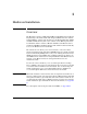
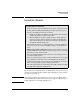
1 Hardware Installation Overview The HP Advanced Services zl Module with Microsoft® Windows Server® 2008 R2 (J9666A) is a zl switch module with integrated Windows Server 2008 R2, Standard Edition, software. The module has a 250GB hard disk drive (HDD) and 4GB of DDR3 memory. The server software on the HDD is prelicensed. You install the Advanced Services Module with Microsoft Windows Server 2008 R2 in an HP E5400 zl or E8200 zl Series switch. The module automatically boots to the Windows Server 2008 R2 OS.
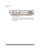
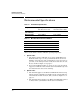
Hardware Installation Overview Module Shutdown button Module Locator LED HDD and Network activity LEDs Management port USB port Module Status LED Figure 1-1. Module Front Panel Additional information about installing and using the module is provided in the HP Advanced Services zl Module with Microsoft Windows Server 2008 R2 Installation and Getting Started Guide, which is available at www.hp.com/ networking/support.
Hardware Installation Install the Module Install the Module Installation Precautions Static electricity can severely damage the electronic components on the module. When handling and installing the module, follow these procedures to avoid damage from static electricity: • Handle the module by its bulkhead or edges and avoid touching the components and the circuitry on the board.
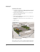
Hardware Installation Install the Module Installation Procedure 1. Use a Torx T-10 or flat-bladed screwdriver to unscrew the screws in the cover plates over the slot where you will install the module. Store the cover plates for possible future use. 2. Hold the module by its bulkhead, taking care not to touch the metal connectors or components on the board. 3. Open the extractor handles. 4.
Hardware Installation Install the Module Verifying That the Module Is Installed Correctly If you have installed the module in a powered off HP zl switch, power up the switch. After the switch powers up, the module will begin to power up. If you have installed the module in a powered on switch, the module begins to power up immediately. The initial bootup takes several minutes.
Hardware Installation Environmental Specifications Environmental Specifications Table 1-2. Environmental Specifications Temperature Operating* Non-Operating 0°C to 45°C (32°F to 113°F) -10°C to 65°C (-10°F to 149°F) Relative humidity (non-condensing) 15% to 90% at 40°C (104°F) 15% to 90% at 65°C (149°F) Maximum altitude 3.0 km (10,000 ft) 4.6 km (15,000 ft) Table 1-3.
Hardware Installation Environmental Specifications Figure 1-3.
Hardware Installation Environmental Specifications 1-8
2 Getting Started Getting Started You can now connect to the Windows Server 2008 R2 that is running on the module. You have several options. Note You can connect to the module’s management port: a. Connect a management station’s Ethernet interface to the management port on the front of your module. b. Configure your management station’s Ethernet interface with IP address, 192.168.2.9, and subnet mask, 255.255.255.252. c. Establish a remote desktop connection to 192.168.2.10. d. Log in.
Getting Started Getting Started If you want to change the IP address, enter these commands: hostzlswitch(hp-svcs-std-C)# windows SBMAdmin You will be prompted for a password. Enter P@ssw0rd. You will then be prompted to change the password.
Getting Started Next Steps Next Steps After you establish the RDP connection, you can begin to manage the server, changing its IP address (if necessary), joining it to the domain, and adding roles to it.
Getting Started Next Steps 2-4
3 Troubleshooting Quick Tips Detailed troubleshooting information for the module is available in its Installation and Getting Started Guide at www.hp.com/networking/support. Some basic tips include: Caution The module fails to boot. Be patient. The module takes several minutes to boot initially, and you must not interrupt this process. You might also check the switch’s software version. It must be K.14.65 or later.
Troubleshooting HP Customer Support Services You receive errors when you enter CLI commands. • If the CLI does not recognize the commands, you might be in the wrong context. – The CLI context ends in (svcs-mod-:App)—You have entered the CLI for the module’s Services OS. To reach the proper context, enter exit and services name hp-svcs-std. – The context ends in (svcs-mod-:SvcOS)—The module is booted to the Services OS. Enter boot ONE-app.
EMC Regulatory Statements A EMC Regulatory Statements U.S.A. - FCC Class A This equipment has been tested and found to comply with the limits for a Class A digital device, pursuant to Part 15 of the FCC Rules. These limits are designed to provide reasonable protection against interference when the equipment is used in a commercial environment.
EMC Regulatory Statements Japan - VCCI Class A Korea Taiwan European Community Declaration of Conformity This product is designed for operation with the HP ProCurve switches that have zl module slots. Refer to the Declarations of Conformity included in the Installation Guides for those products.
Waste Electrical and Electronic Equipment (WEEE) Statements B Waste Electrical and Electronic Equipment (WEEE) Statements Disposal of Waste Equipment by Users in Private Household in the European Union This symbol on the product or on its packaging indicates that this product must not be disposed of with your other household waste.
Waste Electrical and Electronic Equipment (WEEE) Statements Laitteiden hävittäminen kotitalouksissa Euroopan unionin alueella Jos tuotteessa tai sen pakkauksessa on tämä merkki, tuotetta ei saa hävittää kotitalousjätteiden mukana. Tällöin hävitettävä laite on toimitettava sähkölaitteiden ja elektronisten laitteiden kierrätyspisteeseen.
Waste Electrical and Electronic Equipment (WEEE) Statements Smaltimento delle apparecchiature da parte di privati nel territorio dell'Unione Europea Questo simbolo presente sul prodotto o sulla sua confezione indica che il prodotto non può essere smaltito insieme ai rifiuti domestici. È responsabilità dell'utente smaltire le apparecchiature consegnandole presso un punto di raccolta designato al riciclo e allo smaltimento di apparecchiature elettriche ed elettroniche.
Waste Electrical and Electronic Equipment (WEEE) Statements Descarte de Lixo Elétrico na Comunidade Européia Este símbolo encontrado no produto ou na embalagem indica que o produto não deve ser descartado no lixo doméstico comum. É responsabilidade do cliente descartar o material usado (lixo elétrico), encaminhando-o para um ponto de coleta para reciclagem.
Hardware Components Front Panel Buttons, LEDs, and Connectors C Hardware Components Front Panel Buttons, LEDs, and Connectors This section describes the different buttons, LEDs, and connectors on the front panel of a module: ■ Caution Module Shutdown button—This button is used to shut down the module. A message is written to the switch log to indicate the module has shut down.
Hardware Components Front Panel Buttons, LEDs, and Connectors Table C-1. Module LEDs Module LED State Module Statusa (green/ orange) Meaning When the module is first installed, this LED follows the following sequence: 1. Green for ~15s - The module has power. 2. Orange for ~11s - Testing the LED. 3. Green for ~4s - Starting self-test. 4. Orange for ~30s - Self-test in progress. 5. Off - The module is booting the OS. Flashing green Service OS or AppSW is initializing or shutting down.
Hardware Components Internal Ports Internal Ports The module receives traffic from and transmits traffic to its host switch on two internal Ethernet ports, each of which supports 10 Gbps. When a module is installed into the host switch, the switch automatically detects these internal ports and names them according to the slot in which the module is installed. For example, if the module is installed in slot A, the switch references the ports as A1 and A2.
Hardware Components Serial Numbers Disk drive serial and product numbers Figure C-1. Locating the disk drive serial number The serial number for the module is located on the back left corner of the module (Figure C-2). Module serial number SN: SGxxxxxxxx Figure C-2.
Hardware Components Switch LEDs Switch LEDs The following figures show the Test, Fault, and Module Status LEDs on the switches the module can be installed in. Test LED Fault LED Module Status LEDs Figure C-3. Test, Fault, and Module Status LEDs on an E5400 zl Series switch Fault LED Test LED Module Status LEDs Figure C-4.
Hardware Components Replacing or Removing a Module Replacing or Removing a Module It is highly recommended that the module be shutdown before replacing or removing it.
Hardware Components Replacing Field Replaceable Units (FRUs) Caution For proper cooling and reduction of electromagnetic emissions, ensure that a slot cover is installed on any unused slot. In an operational chassis, an unused slot should be covered if it is not used for more than 2 minutes.
Hardware Components Replacing Field Replaceable Units (FRUs) C-8
Software Components Updating Switch Software D Software Components Updating Switch Software The HP Advanced Services zl Module with Microsoft® Windows Server® requires switch software version K.14.65 or later to be installed in the switch. Version K.15.03 or greater is recommended if the module is installed in an HP E8200 zl switch with dual management modules. K.15.03 will gracefully shutdown and restart the module in the event of a management module failover. (Version K.14.
Software Components Updating the Service OS Updating the Service OS There are two ways to update the Service OS: Note ■ via FTP: used when a local FTP server is accessible from the module ■ via USB: used when a local FTP server is not accessible from the module The process of updating the Service OS is faster if the switch is accessed via Telnet or SSH; the serial console slows down the writing of characters to the screen, causing a significantly slower installation speed, especially if the switch co
Software Components Updating the Service OS hostswitch(svcs-mod-C:SvcOS)# show images 5. Update the Service OS. hostswitch(svcs-mod-C:SvcOS)# update ServiceOS 6. Boot the Service OS (optionally, boot the AppSW): hostswitch(svcs-mod-C:SvcOS)# boot ServiceOS Changing boot from CF Service OS to Service OS. System will be rebooted. Do you want to continue [y/n]? y Rebooting 7.
Software Components Device Disable 9. Unmount the USB flash drive. hostswitch(ssvcs-mod-C:SvcOS)# usb unmount 10. Remove the USB flash drive from the module. 11. For the rest of the procedure, go to Step 4. on page D-2. Device Disable The module offers improved security and reliability. In case there is no physical security on the chassis, the USB and the shutdown button can be disabled to prevent unauthorized or undesired access. Both the USB and the shutdown button are enabled by default.
Index HDD Activity … C-2 Meaning … C-2 Module Locator … C-2 Module Status … 1-5, C-2 Network Activity … C-2 State … C-2 Switch … C-5 Test … 1-5 C CLI Command boot ONE-app … D-3 shutdown … C-1, C-6 Command Line Interface (CLI) … 1-1 show version … D-1 Switch … C-2, D-1 credentials … 2-1 M D Device Disable … D-4 DHCP … 2-1, 3-1 management port … 2-1, C-1 maximum modules … 1-6 Module Front Panel … C-1 Module Shutdown … C-1 E EMC Regulatory Statements … A-1 environmental specifications … 1-6 O F ONE-app
U USB slot SBM … C-1 V VLAN … 2-1 W warranty … 1-1 Waste Electrical and Electronic Equipment (WEEE) Statements … B-1 WinPcap caution … 2-3 Z zl Switch … 1-3, 1-5, C-5 2 – Index
center Connection Manager Controller Management and Configuration
Technology for better business outcomes To learn more, visit www.hp.com/networking © Copyright 2011 Hewlett-Packard Development Company, L.P. The information contained herein is subject to change without notice. The only warranties for HP products and services are set forth in the express warranty statements accompanying such products and services. Nothing herein should be construed as constituting an additional warranty. HP will not be liable for technical or editorial errors or omissions contained herein.