
HP Survivable Branch Communication zl Module powered by Microsoft Lync Planning and Design Guide 2011-02


1-3
SBM Overview
SBM Components
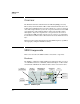
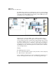
PCIe Slots
The module includes two PCIe slots, in which you install telephony cards.
These cards provide the interfaces for public switch telephone network
(PSTN) connections.
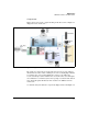
Ports
The 1 Gbps management port, which you see on the SBM’s front panel,
provides direct management access to the SBM, allowing a network adminis-
trator or support person to reach the SBM even if its network connectivity has
failed. The management port does not connect to the switch backplane and
does not forward traffic beyond the SBM itself. (This port is enabled by
default.)
The SBM includes two internal 10G Ethernet ports, port 1 and port 2, which
you cannot see in the picture. These ports connect the module to the back-
plane of the switch in which the module is installed.
The Windows OS that runs on the SBM (see the section below) maps these
three ports to local area network (LAN) interfaces. By default, the interface
for the internal port 2 is enabled while the interface for the internal port 1 is
disabled. Usually, you are only concerned with the interface mapped to the
internal port 2. (As mentioned earlier, the management port on the front of
the module does not forward traffic past the SBM.)
Port 2 carries this traffic:
■ Traffic to and from Lync clients and IP phones
■ Traffic to and from other components of the Lync solution such as the
main site’s server pool
■ Management traffic to and from the SBM (see “Planning Ease of Manage-
ment” on page 2-49 of Chapter 2: “Design Considerations” to learn more
about the different ways to manage the SBM)
Caution You must never disable port 2.
In addition, HP recommends that you leave port 1 disabled because the SBM
solution is designed for one port only and it is highly unlikely that port 2 will
fail. Enabling port 1 can cause issues with DNS, and you do so at your own risk.