
HP Survivable Branch Communication zl Module powered by Microsoft Lync Planning and Design Guide 2011-02

4-60
Example Solutions
Solution
Ready the Branch LAN Infrastructure
This section includes instructions for configuring the networking switch (in
which the SBM is installed) at the Seattle branch office—in this solution, an
HP E8206 zl switch.
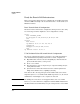
Basic Network Switch Configuration
Listed below is the switch’s basic configuration, which provides connectivity
for end users (your switch might have other configurations as well):
vlan 1
name “DEFAULT_VLAN”
no untagged a1-a24,b1-b24,e2,d1-d2,f1-f24
exit
vlan 42
name “Data”
ip address 10.4.2.2 255.255.255.0
tagged f24
untagged a1-a24,b1-b24,f1-f23
exit
ip default-router 10.4.2.1
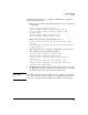
UC&C Solution-Related Network Switch Configuration
The switch configurations in this section relate to the Unified Communica-
tions and Collaboration (UC&C) solution. These switch configurations:
■ Map Differentiated Services Code Point (DSCP) 40, with which the IP
phones mark their traffic, to 802.1p level 6
■ Create a voice VLAN
■ Tag all ports that connect to IP phones (or computers running the Lync
client) with that VLAN
■ Synchronize the switch time with the domain controller (which runs
Simple Network Time Protocol [SNTP] by default)
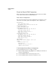
If the branch office already participated in the UC&C solution, the switch
might already have a voice VLAN and the DSCP map. In that case, the switch
administrator would simply need to complete the last task.
Note The SBM’s port 2 must also be an untagged member of the voice VLAN.
However, you cannot make this configuration until the SBM is installed. The
installation instructions will remind you to place this port in the correct VLAN.