
HP Survivable Branch Communication zl Module powered by Microsoft Lync Planning and Design Guide 2011-02


1-21
SBM Overview
SBM PSTN Capabilities
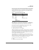
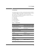
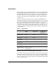
Table 1-1 shows the supported settings on the HP Media Gateway and T1/E1
Telephony Cards. If you need more information about line coding, frame
format, and ISDN switch types, you can read the sections below. However,
typically you do not choose these settings yourself. You simply match the
settings that your carrier tells you to use.
Table 1-1. Supported T1/E1 Settings on the SBM
Line Coding. Line coding defines how digital signals are configured for
transport through a physical transmission medium. Line coding schemes use
electrical signals to represent the logical 0 and 1 bits in a data stream.
E1- and T1-carrier lines have slightly different options for line coding.
E1-carrier lines use the following line coding schemes:
■ Alternate mark inversion (AMI)
■ High-density bipolar of order 3 (HDB3)
AMI uses alternating positive and negative voltage (referred to as alternating
polarity or bipolarity) to represent logical ones, and zero voltage to represent
logical zeros. Because AMI uses zero voltage for logical zeros, it can cause
synchronization loss between peers at each end of a WAN connection if a data
stream contains a long string of logical zeros.
Although HDB3 is based on AMI, HDB3 prevents synchronization loss by
limiting the number of consecutive zero signals in a data stream to three. HDB3
replaces four logical zeros with three signals at zero voltage and a violation
bit with the same polarity as the last AMI logical one detected.
T1-carrier lines use the following line coding schemes:
■ AMI
■ Bipolar 8-Zero Substitution (B8ZS)
Parameter T1 E1
Line coding ESF
D4
CRC4
Non-CRC4
Frame
format
B8ZS
AMI
HDB3
AMI
Switch type 4ESS
5ESS
DMS100
National ISDN (NI2)
Net5 (ETSI, Euro ISDN)