HP VPN Firewall Appliances Getting Started Guide Part number: 5998-4163 Software version: F1000-A-EI/F1000-S-EI (Feature 3726) F1000-E (Release 3177) F5000 (Feature 3211) F5000-S/F5000-C (Release 3808) VPN firewall modules (Release 3177) 20-Gbps VPN firewall modules (Release 3817) Document version: 6PW101-20130923
Legal and notice information © Copyright 2013 Hewlett-Packard Development Company, L.P. No part of this documentation may be reproduced or transmitted in any form or by any means without prior written consent of Hewlett-Packard Development Company, L.P. The information contained herein is subject to change without notice.
Contents Overview ······································································································································································ 1 F1000-A-EI/F1000-S-EI ···················································································································································· 1 Overview ···············································································································································
Configuring none authentication for AUX login ································································································· 40 Configuring password authentication for AUX login························································································· 41 Configuring scheme authentication for AUX login ···························································································· 42 Configuring common settings for AUX login (optional)···························
Configuring the time zone and daylight saving time ························································································ 86 Configuring the system time at the CLI························································································································· 87 Configuration guidelines ······································································································································ 87 Configuration procedure ···················
Returning to user view from any other view ····································································································· 124 Accessing the CLI online help ····································································································································· 125 Entering a command···················································································································································· 126 Editing a command line ·
Overview This documentation is applicable to the following firewall products: • F1000-A-EI • F1000-S-EI • F1000-E • F5000 • F5000-C • F5000-S • VPN firewall module • 20-Gbps VPN firewall module You can configure most of the firewall functions in the Web interface and some functions at the command line interface (CLI). Each function configuration guide specifies clearly whether the function is configured in the Web interface or at the CLI.
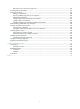
Figure 1 Front view (1) Combo interfaces (2) Console port (CONSOLE) (3) USB port (reserved for future use) Figure 2 Rear view (1) Power module slot 1 (PWR1) (supports AC/DC power modules) (2) Power module slot 2 (PWR2) (supports AC/DC power modules) (3) Interface module slot 2(Slot 2) (4) Grounding screw (5) Interface module slot 1 (Slot 1) F1000-E Overview The F1000-E is designed for large- and medium-sized networks. It supports the following functions: • Traditional firewall functions.
Support for management by its own Web-based management system or by IMC. • The F1000-E uses a multi-core processor and provides the following interfaces: • Four combo interfaces, for fiber/copper port switching. • Two high-speed interface module (HIM) expansion slots, which support the following interface modules: 4GBE, 8GBE, HIM-1EXP, and 4GBP.
• Protection against external attacks, internal network protection, traffic monitoring, email filtering, Web filtering, application layer filtering • ASPF • Multiple types of VPN services, such as L2TP VPN, GRE VPN, IPsec VPN, and dynamic VPN • RIP/OSPF/BGP routing, routing policy, and policy-based routing • Power module 1+1 redundancy backup (AC+AC or DC+DC) • Multiple types of service interface cards • High availability functions, such as stateful failover and VRRP Appearance Figure 5 Front
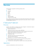
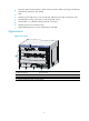
Figure 6 Rear view (1) Warning label (2) Rear chassis cover handle (3) (Optional) Upper slide rail for the air filter (4) (Optional) Air filter (5) (Optional) Air filter (6) Chassis handle (7) Weight support warning label (Max. weight of 50 kg/110.
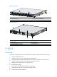
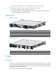
Appearance Figure 7 Front view (1) 10/100/1000BASE-T copper Ethernet port (2) 1000BASE-X fiber Ethernet port (3) 10GBASE-R fiber Ethernet port (4) Console port (CONSOLE) (5) USB port (reserved for future use) (6) Status LEDs (7) Interface module slot Figure 8 Rear view 1 2 3 4 (1) Fan tray (2) Power module slot 1 (3) Power module slot 2 (4) Grounding screw VPN firewall modules Overview The VPN firewall modules are developed based on the Open Application Architecture (OAA) for carrier-level c
A VPN firewall module can be installed in the HP 5800/7500/9500/12500 Switch Series or a 6600/8800 router. A switch or router can be installed with multiple VPN firewall modules to expand the firewall processing capability for future use. The main network device (switch or router) and the VPN firewall modules together provide highly integrated network and security functions for large networks. The VPN firewall modules support the following functions and features: • Traditional firewall functions.
Figure 10 VPN firewall module for 7500/9500/12500 series switches (1) CF ejector button (2) CF card slot (CF CARD) (3) CF card LED (CFS) (4) Console port (CONSOLE) (5) USB port 1 (reserved for future use) (6) USB port 2 (reserved for future use) (7) Copper Ethernet port 1 (10/100/1000BASE-T) (8) Copper Ethernet port 2 (10/100/1000BASE-T) (9) Copper Ethernet port 1 LED (LINK) (10) Copper Ethernet port 1 LED (ACT) (11) Copper Ethernet port 2 LED (LINK) (12) Copper Ethernet port 2 LED (ACT) (13) C
Figure 11 VPN firewall module for 6600/8800 routers (1) CF ejector button (2) CF card slot (CF CARD) (3) CF card LED (CF) (4) Console port (CONSOLE) (5) USB port 1 (reserved for future use) (6) USB port 0 (reserved for future use) (7) Copper Ethernet port 1 (GE1) (8) Copper Ethernet port 0 (GE2) (9) Copper Ethernet port 1 LED (LINK) (10) Copper Ethernet port 1 LED (ACT) (11) Copper Ethernet port 0 LED (LINK) (12) Copper Ethernet port 0 LED (ACT) (13) Copper Ethernet port 3 (copper combo port)
implement security functions (such as firewall and VPN) in the HP 7500/10500/12500 switch series, integrating security protection with network functions. The 20-Gbps VPN firewall modules support the following functions: • External attack protection, internal network protection, traffic monitoring, URL filtering, application layer filtering. • ASPF • Email alarm, attack log, stream log, and network management monitoring.
Figure 13 20-Gbps VPN firewall module for 12500 switches (1) Console port (CONSOLE) (2) USB port (reserved for future use) (3) Copper combo port (10/100/1000BASE-T) (4) Copper combo port LED (LINK/ACT) (5) Fiber combo port (1000BASE-X) (6) Fiber combo port LED (LINK/ACT) (7) Alarm LED (ALM) (8) System LED (RUN) (9) Ejector lever (10) Captive screw Application scenarios F1000-A-EI/F1000-S-EI application scenarios Firewall application With powerful filtering and management functions, the F1000-A-EI
Figure 14 Network diagram Virtual firewall application The F1000-A-EI/F1000-S-EI supports the virtual firewall function. You can create multiple virtual firewalls on one firewall. Each virtual firewall can have its own security policy and can be managed independently. Figure 15 Network diagram VPN application The F1000-A-EI/F1000-S-EI supports VPN functions, helping branch offices and remote users securely access the resources in the headquarters and those in their own networks.
Figure 16 Network diagram F1000-E application scenarios Deployed at the egress of an enterprise network, F1000-E firewalls can protect against external attacks, ensure security access from the external network to the internal network resources (such as servers in the DMZ zone) through NAT and VPN functions, and control access to the internal network by using security zones. You can deploy two firewalls in the network for redundancy backup to avoid a single point failure.
F5000 application scenarios Large data centers are connected to the 10G core network usually through a 10G Ethernet. The F5000 firewall has a 10G processing capability and abundant port features. It can be deployed at the egress of a network to protect security for the internal network. You can deploy two firewalls to implement stateful failover. • Active-active stateful failover can balance user data. • Active-standby stateful failover improves availability of the firewalls.
Figure 19 Network diagram VPN application An F5000-S or F5000-C at the egress of headquarters provides powerful VPN functions for branches and mobile employee to access the headquarters securely. Figure 20 Network diagram F1000-A-EI F1000-A-EI F1000-A-EI Virtual firewall application An F5000-S or F5000-C runs multiple virtual firewalls. Each virtual firewall can have its own security policy and can be managed separately.
Figure 21 Network diagram VPN firewall modules application scenarios VPN firewall modules work with the main network devices (such as 5800/7500/9500/12500 switches and 6600/8800 routers). Deployed at the egress of a network, the firewall modules can protect against external attacks and implement security access control of the internal network by using security zones. You can meet the development of the network simply by installing more firewall modules to a switch or router.
20-Gbps VPN firewall modules application scenarios Cloud computing data center application The 20-Gbps VPN firewall modules can provide high-performance firewall functions. They also support the virtual firewall function. A 20-Gbps VPN firewall module can be virtualized into multiple logical firewalls. Each virtual firewall has its own security policy and is managed independently. The virtual firewall function well satisfies the multi-tenant requirements in cloud computing data centers.
Figure 24 Network diagram Remote access application The 20-Gbps VPN firewall module supports VPN functions, helping branch offices and remote users securely access the resources in the headquarters Figure 25 Network diagram 18
Login overview This chapter describes the available login methods and introduces the related concepts. Login methods at a glance You can access the device through the console port or the Web interface at the first login. After login, you can configure other login methods on the device, such as AUX, Telnet, and SSH.
Login method Default setting and configuration requirements By default, SNMP login is disabled. To use SNMP service, complete the following configuration tasks: Accessing the device through SNMP • Assign an IP address to an interface of the device and make sure the interface and the NMS can reach each other. By default, only interface GigabitEthernet 0/0 is assigned an IP address (192.168.0.1/24). • Configure SNMP basic parameters.
user interfaces. You can use the display user-interface command without any parameters to view supported user interfaces and their absolute numbers. A relative number uniquely identifies a user interface among all user interfaces that are the same type. The number format is user interface type + number: • Console user interface—CON0. • AUX user interface—AUX 0. • VTY user interfaces—Numbered starting from 0 and incrementing by 1.
Logging in to the CLI By default, the first time you access the CLI you must log in through the console port. At the CLI, you can configure Telnet or SSH for remote access. Logging in through the console port for the first time To log in through the console port, make sure the console terminal has a terminal emulation program (for example, HyperTerminal in Windows XP). In addition, the port settings of the terminal emulation program must be the same as the default settings of the console port in Table 3.
or some other operating system, obtain a third-party terminal control program first, and then follow the user guide or online help to log in to the device.
Figure 29 Setting the properties of the serial port 5. Power on the device and press Enter at the prompt. Figure 30 CLI 6. At the default user view prompt , enter commands to configure the device or view the running status of the device. To get help, enter ?. Configuring console login control settings The following authentication modes are available for controlling console logins: • None—Requires no authentication. This mode is insecure. • Password—Requires password authentication.
Scheme—Uses the AAA module to provide local or remote console login authentication. You must provide a username and password for accessing the CLI. For more information about authentication modes and parameters, see Access Control Configuration Guide. Keep your username and password. • By default, console login does not require authentication. Any user can log in through the console port without authentication and have user privilege level 3.
Configuring password authentication for console login Step Command Remarks 1. Enter system view. system-view N/A 2. Enter console user interface view. user-interface console first-number [ last-number ] N/A 3. Enable password authentication. authentication-mode password By default, you can log in to the device through the console port without authentication and have user privilege level 3 after login. 4. Set a password.
Step 3. Enable scheme authentication. Command Remarks authentication-mode scheme Whether local, RADIUS, or HWTACACS authentication is adopted depends on the configured AAA scheme. By default, console login users are not authenticated. Optional. 4. Enable command authorization. command authorization By default, command authorization is disabled. The commands available for a user only depend on the user privilege level. Optional. 5. Enable command accounting. command accounting 6.
The next time you attempt to log in through the console port, you must provide the configured login username and password. Configuring common console user interface settings (optional) Some common settings configured for a console user interface take effect immediately and can interrupt the console login session. To save you the trouble of repeated re-logins, use a login method different from console login to log in to the device before you change console user interface settings.
Step Command Remarks By default, the terminal display type is ANSI. 9. Specify the terminal display type. 10. Configure the user privilege level for login users. terminal type { ansi | vt100 } user privilege level level 11. Set the maximum number of lines to be displayed on a screen. screen-length screen-length 12. Set the size of command history buffer. history-command max-size value 13. Set the idle-timeout timer.
Table 5 shows the Telnet server and client configuration required for a successful Telnet login. Table 5 Telnet server and Telnet client configuration requirements Device role Requirements Enable Telnet server. Telnet server Assign an IP address to an interface of the device, and make sure the Telnet server and client can reach each other. By default, only interface GigabitEthernet 0/0 is assigned an IP address (192.168.0.1/24). Configure the authentication mode and other settings.
Authentication mode Configuration tasks Reference Enable scheme authentication on the VTY user interface. Configure local or remote authentication settings. To configure local authentication: Scheme 1. Configure a local user and specify the password. 2. Configure the device to use local authentication. To configure remote authentication: 1. Configure the RADIUS or HWTACACS scheme on the device. 2. Configure the username and password on the AAA server. 3.
Configuring password authentication for Telnet login Step Command Remarks 1. Enter system view. system-view N/A 2. Enable Telnet server. telnet server enable By default, the Telnet server function is disabled. 3. Enter one or multiple VTY user interface views. user-interface vty first-number [ last-number ] N/A 4. Enable password authentication. authentication-mode password By default, the authentication mode for the VTY user interfaces is scheme. 5. Set a password.
• To make the command authorization or command accounting function take effect, apply an HWTACACS scheme to the intended ISP domain. This scheme must specify the IP address of the authorization server and other authorization parameters. • If the local authentication scheme is used, use the authorization-attribute level level command in local user view to set the user privilege level on the device.
Step Command Remarks 10. Set a password. password { cipher | simple } password By default, the password for system-predefined user admin is admin, and no password is set for any other local user. 11. Specify the command level of the local user. authorization-attribute level level Optional. By default, the command level is 0. 12. Specify Telnet service for the local user.
Step Command Remarks N/A 2. Enter one or multiple VTY user interface views. user-interface vty first-number [ last-number ] 3. Enable the terminal service. shell Optional. By default, terminal service is enabled. Optional. Enable the user interfaces to support Telnet, SSH, or both of them. protocol inbound { all | ssh | telnet } 5. Define a shortcut key for terminating tasks. escape-key { default | character } 6. Configure the type of terminal display. 4.
Using the device to log in to a Telnet server You can use the device as a Telnet client to log in to a Telnet server. If the server is located in a different subnet than the device, make sure the two devices have routes to reach each other. Figure 32 Telnetting from the device to a Telnet server To use the device to log in to a Telnet server: Step Command Remarks N/A 1. Enter system view. system-view 2. Specify the source IPv4 address or source interface for outgoing Telnet packets.
Table 7 SSH server and client requirements Device role Requirements SSH server Assign an IP address to an interface of the device, and make sure the interface and the client can reach each other. By default, only interface GigabitEthernet 0/0 is assigned an IP address (192.168.0.1/24). Configure the authentication mode and other settings. SSH client If a host operates as an SSH client, run the SSH client program on the host. Obtain the IP address of the interface on the server.
Step Command Remarks 4. Enter one or multiple VTY user interface views. user-interface vty first-number [ last-number ] N/A 5. Enable scheme authentication. authentication-mode scheme By default, the authentication mode for VTY user interfaces is scheme. 6. Enable the user interfaces to support Telnet, SSH, or both of them. Optional. protocol inbound { all | ssh } By default, both Telnet and SSH are supported. Optional. 7. Enable command authorization.
Step Command Remarks 15. Exit to system view. quit N/A 16. Create an SSH user, and specify the authentication mode for the SSH user. ssh user username service-type stelnet authentication-type { password | { any | password-publickey | publickey } assign publickey keyname } N/A 17. Configure common settings for VTY user interfaces. See "Configuring common VTY user interface settings (optional)." Optional.
As shown in Figure 35, to perform local login through the AUX port, use the same cable and login procedures as console login. For a device with separate console and AUX ports, you can use both ports to log in to the device. Figure 35 AUX login diagram To control AUX logins, configure authentication and user privilege for AUX port users. By default, password authentication applies to AUX login, but no login password is configured. To allow AUX login, you must configure a password.
Step Command Remarks 2. Enter one or more AUX user interface view. user-interface aux first-number [ last-number ] N/A 3. Enable none authentication mode. authentication-mode none By default, password authentication is enabled for AUX login users. 4. Configure common settings for AUX login. See "Configuring common settings for AUX login (optional)." Optional. The next time you attempt to log in through the AUX port, you do not need to provide any username or password, as shown in Figure 36.
The next time you attempt to log in to CLI through the AUX port, you must provide the configured login password, as shown in Figure 37. Figure 37 Password authentication interface for AUX login 2010-2013 Configuring scheme authentication for AUX login When scheme authentication is used, you can choose to configure the command authorization and command accounting functions.
Step 3. Enable scheme authentication. Command Remarks authentication-mode scheme By default, password authentication is enabled on AUX user interfaces. Optional. 4. Enable command authorization. command authorization By default, command authorization is disabled. The commands available for a user only depend on the user privilege level. Optional. 5. Enable command accounting. command accounting 6. Exit to system view. quit By default, command accounting is disabled.
Figure 38 Scheme authentication interface for AUX login 2010-2013 Configuring common settings for AUX login (optional) Some common settings configured for an AUX user interface take effect immediately and can interrupt the login session. To save you the trouble of repeated re-logins, use a login method different from AUX login to log in to the device before you change AUX user interface settings.
Step Command Remarks The default is 1. 6. Specify the number of stop bits. stopbits { 1 | 1.5 | 2 } Stop bits indicate the end of a character. The more the bits, the slower the transmission. By default, the number of data bits in each character is 8. The setting depends on the character coding type. For example, you can set it to 7 if standard ASCII characters are to be sent, and set it to 8 if extended ASCII characters are to be sent. 7. Specify the number of data bits in each character.
Parameter Default Bits per second 9600 bps Flow control • Independent AUX port: On • Console and AUX integrated port: Off Parity None Stop bits 1 Data bits 8 Login procedure To log in through the AUX port: • Complete the authentication settings on the AUX user interface. By default, password authentication is enabled, but no password is set. To use password authentication, you must set a password for password authentication.
3. If the PC is off, turn on the PC. 4. Launch the terminal emulation program and configure the communication properties on the PC. Figure 40 through Figure 42 show the configuration procedure on Windows XP HyperTerminal. Make sure the port settings are the same as the common AUX port settings on the device. If the default settings are used, see Table 9. On Windows Server 2003, add the HyperTerminal program first, and then log in to and manage the device as described in this document.
Figure 42 Setting the properties of the serial port 5. Power on the device and press Enter at the prompt. Figure 43 CLI 6. At the default user view prompt , enter commands to configure the device or check the running status of the device. To get help, enter ?. Displaying and maintaining CLI login Task Command Remarks Display information about the user interfaces that are being used. display users [ | { begin | exclude | include } regular-expression ] Available in any view.
Task Command Remarks Display information about all user interfaces the device supports. display users all [ | { begin | exclude | include } regular-expression ] Available in any view. Display user interface information. display user-interface [ num1 | { aux | console | vty } num2 ] [ summary ] [ | { begin | exclude | include } regular-expression ] Available in any view. Display the configuration of the device when it serves as a Telnet client.
Logging in to the Web interface The device provides a built-in Web server for you to configure the device through a Web browser. Web login is by default enabled. Configuration guidelines • The Web-based configuration interface supports the operating systems of Windows XP, Windows 2000, Windows Server 2003 Enterprise Edition, Windows Server 2003 Standard Edition, Windows Vista, Windows 7, Linux, and MAC OS. • The Web-based configuration interface supports the browsers of Microsoft Internet Explorer 6.
Hardware Management interface F5000-S/F5000-C M-GigabitEthernet 0/0 VPN firewall modules • GigabitEthernet 0/0 on firewall modules for HP 5800 and HP 6600 • GigabitEthernet 0/1 on firewall modules for other devices 20-Gbps VPN firewall modules GigabitEthernet 0/1 If the HTTP service is disabled, you can enable it by following the steps provided in "Configuring HTTP login." You can also see Access Control Configuration Guide.
Figure 45 Adding a local user 3. Configure a management account as follows: { Enter the username. { Select the privilege level Management. { Select the service type Web. Available service types depend on the device model. See Getting Started Guide. { Enter and confirm the password. For security purposes, enter a password that is complex. { Select a password encryption mode. 4. Click Apply to create the account. 5.
3. Click the icon for the default account admin and confirm the operation. Web interface The Web interface includes three parts: navigation tree, title area, and body area. Figure 47 Web interface (1) Navigation area (2) Body area (3) Title area • Navigation area—Web-based network management function menus in the form of a navigation tree, where you can select function menus as needed. The result is displayed in the body area. • Body area—Area where you can configure and display a function.
HTTPS uses SSL to encrypt data between the client and the server for data integrity and security, and is more secure than HTTP. You can define a certificate attribute-based access control policy to allow only legal clients to access the device. HTTP login and HTTPS login are separate login methods. To use HTTPS login, you do not need to configure HTTP login. Table 10 shows the basic Web login configuration requirements.
Step Command Remarks 8. Create a local user and enter local user view. local-user user-name By default, a local user named admin exists. 9. Configure a password for the local user. password { cipher | simple } password By default, the password for system-predefined user admin is admin, and no password is set for any other local user. authorization-attribute level level No command level is configured for the local user. 11. Specify the Telnet service type for the local user.
Step Command Remarks Optional. 1. Specify a fixed verification code for Web login. web captcha verification-code By default, a Web user must enter the verification code indicated on the login page to log in. This command is available in user view. 2. Enter system view. N/A system-view Optional. By default, the HTTPS service is not associated with any SSL server policy, and the device uses a self-signed certificate for authentication. 3. Associate the HTTPS service with an SSL server policy.
Step 6. 7. Command Specify the HTTPS service port number. Associate the HTTPS service with an ACL. Remarks ip https port port-number Optional. The default HTTPS service port is 443. By default, the HTTPS service is not associated with any ACL. ip https acl acl-number Associating the HTTPS service with an ACL enables the device to allow only clients permitted by the ACL to access the device. Optional. By default, a user must enter the correct username and password to log in through HTTPS.
Displaying and maintaining Web login Task Command Remarks Display information about Web users. display web users [ | { begin | exclude | include } regular-expression ] Available in any view. Display HTTP state information. display ip http [ | { begin | exclude | include } regular-expression ] Available in any view. Display HTTPS state information. display ip https [ | { begin | exclude | include } regular-expression ] Available in any view.
2. Verify the configuration: # On the PC, launch a Web browser and enter the IP address of the interface in the address bar. The Web login page appears, as shown in Figure 49. Figure 49 Web login page # Enter the username, password, verification code, select English, and click Login. The homepage appears. After login, you can configure device settings through the Web interface.
[Firewall-pki-entity-en] fqdn ssl.security.com [Firewall-pki-entity-en] quit # Create a PKI domain, specify the trusted CA as new-ca, the URL of the server for certificate request as http://10.1.2.2/certsrv/mscep/mscep.dll, authority for certificate request as RA, and the entity for certificate request as en. [Firewall] pki domain 1 [Firewall-pki-domain-1] ca identifier new-ca [Firewall-pki-domain-1] certificate request url http://10.1.2.2/certsrv/mscep/mscep.
[Firewall-luser-usera] authorization-attribute level 3 2. Configure the host (HTTPS client): On the host, run the IE browser, and then enter http://10.1.2.2/certsrv in the address bar and request a certificate for the host as prompted. 3. Verify the configuration: Enter https://10.1.1.1 in the address bar, and select the certificate issued by new-ca. When the Web login page of the firewall appears, enter the username usera and password 123 to log in to the Web management page.
Figure 51 Internet Explorer setting (1) 3. Click Custom Level. The dialog box Security Settings appears. 4. Enable Run ActiveX controls and plug-ins, script ActiveX controls marked safe for scripting and active scripting.
Figure 52 Internet Explorer setting (2) 5. Click OK in the Security Settings dialog box. Configuring Firefox Web browser settings 1. Open the Firefox Web browser, and select Tools > Options. 2. Click the Content tab, select the Enable JavaScript box, and click OK.
Figure 53 Firefox Web browser setting 64
Accessing the device through SNMP NOTE: Accessing the device through SNMP is not supported in FIPS mode. You can run SNMP on an NMS to access the device MIB and perform GET and SET operations to manage and monitor the device. The device supports SNMPv1, SNMPv2c, and SNMPv3, and can work with various network management software products, including IMC. For more information about SNMP, see System Management and Maintenance Configuration Guide. By default, SNMP access is disabled.
Step Command Remarks Optional. 2. 3. 4. By default, the SNMP agent is disabled. Enable the SNMP agent. snmp-agent Configure an SNMP group and specify its access right. snmp-agent group v3 group-name [ authentication | privacy ] [ read-view read-view ] [ write-view write-view ] [ notify-view notify-view ] [ acl acl-number | acl ipv6 ipv6-acl-number ] * By default, no SNMP group is configured. Add a user to the SNMP group.
Step Command Remarks • (Method 1) Specify the SNMP NMS access right directly by configuring an SNMP community: snmp-agent community { read | write } community-name [ mib-view view-name ] [ acl acl-number | acl ipv6 ipv6-acl-number ] * • (Method 2) Configure an SNMP 4. Configure the SNMP access right. group and add a user to the SNMP group: a.
# Add a user to the SNMP group. [Sysname] snmp-agent usm-user v3 managev3user managev3group 2. Configure the NMS: Make sure the NMS has the same SNMP settings, including the username as the firewall. If not, the firewall cannot be discovered or managed by the NMS. 3. Use the network management station to discover, query, and configure the firewall. For more information, see the NMS manual.
Logging in to the firewall module from the network device Feature and hardware compatibility Hardware Feature compatibility F1000-A-EI/F1000-S-EI No F1000-E No F5000 No F5000-S/F5000-C No VPN firewall modules Yes 20-Gbps VPN firewall modules Yes This chapter describes how to log in to the firewall module from the network device. Other login methods for the firewall module are the same as a firewall.
To log in to the firewall module from the network device: Task Command Remarks • In standalone mode: Log in to the firewall module from the network device. oap connect slot slot-number • In IRF mode: oap connect chassis chassis-number slot slot-number Available in user view of the network device (switch or router). After login, the terminal screen displays the CLI of the firewall module. To return to the CLI on the device, press Ctrl+K.
The management IP address configured on the device for the firewall module must be the same as the management IP address configured on the firewall module. To configure the management IP address of the firewall module on the device: Step 1. Enter system view. Command Remarks system-view N/A • In standalone mode: 2. Configure a management IP address for the firewall module.
The monitoring timer is used to periodically trigger the ACSEI client to send monitoring requests to the ACSEI server. You cannot set this timer. • ACSEI startup and running ACSEI starts up and runs in the following procedures: The firewall module runs the ACSEI client application to enable ACSEI client. Start up the network device and enable the ACSEI server function on it. The ACSEI client multicasts a registration request.
Displaying and maintaining ACSEI server and client Task Command Remarks Display ACSEI client summary. display acsei client summary [ client-id ] Available in any view. Display ACSEI client information. display acsei client info [ client-id ] Available in any view. Display ACSEI client information. display acsei-client information Available in any view. Display current ACSEI client state. display acsei-client status Available in any view.
oap connect slot 3 Connected to OAP! 2. Configure the clock synchronization timer and the monitoring timer on the network device: # Enable ACSEI server. system-view [Switch] acsei server enable # Enter ACSEI server view. [Switch] acsei server # Set the clock synchronization timer to 10 minutes. [Switch-acsei server] acsei timer clock-sync 10 # Set the monitoring timer to 10 seconds. [Switch-acsei server] acsei timer monitor 10 3.
Basic configuration Overview Basic configuration information include: • Device name and login password—Modify the system name and the password of the current user. • Service management—Specify whether to enable the services like FTP, Telnet, HTTP, and HTTPS, and set port numbers for HTTP and HTTPS. • Interface IP address—Configure IP addresses for Layer 3 Ethernet interfaces and VLAN interfaces. • NAT—Configure dynamic NAT, internal server translation, and related parameters.
Figure 57 Basic configuration wizard—1/6 3. Click Next. The page for basic configuration appears.
4. Configure the parameters as described in Table 11. Table 11 Configuration items Item Description Sysname Enter the system name. Modify Current User Password Specify whether to modify the login password of the current user. New Password To modify the password of the current user, set the new password and the confirm password, and the two passwords must be identical. IMPORTANT: Confirm Password Password Encryption 5.
Item Telnet Description Specify whether to enable Telnet on the device. Disabled by default. Specify whether to enable HTTP on the device, and set the HTTP port number. Enabled by default. IMPORTANT: HTTP • If the current user has logged in to the Web interface through HTTP, disabling HTTP or modifying the HTTP port number will result in disconnection with the device. Therefore, perform the operation with caution. • When you modify a port number, make sure the port number is not used by another service.
Figure 60 Basic configuration wizard—4/6 (interface IP address configuration) 8. Assign IP addresses to the interfaces. Table 13 Configuration items Item Description Set the approach for obtaining the IP address, including: • None—The IP address of the interface is not specified. The interface has no IP address. • Static Address—Specify the IP address for the IP Configuration interface manually. If you select this item, specify both the IP address and the mask.
Figure 61 Basic configuration wizard—5/6 (NAT configuration) 10. Configure the parameters as described in Table 14. Table 14 Configuration items Item Description Interface Select an interface on which the NAT configuration will be applied. Specify whether to enable dynamic NAT on the interface. Dynamic NAT If dynamic NAT is enabled, the IP address of the interface will be used as the IP address of a matched packet after the translation. By default, dynamic NAT is disabled.
Item Description External IP: Port When you enable the internal server, set the valid IP address and service port number for the external access. Internal IP: Port If you enable the internal server, set the IP address and service port number for the server on the internal LAN. 11. Click Next. The page listing all configurations you have made in the basic configuration wizard appears.
Step Command Remarks • To configure a static NAT mapping: a. nat static local-ip [ vpn-instance local-name ] global-ip [ vpn-instance global-name ] b. interface interface-type interface-number 4. Configure NAT. c. nat outbound static • To configure dynamic NAT: a. interface interface-type interface-number Optional. By default, NAT is not configured on an interface. b.
Step Command Remarks import interface interface-type interface-number [ vlan vlan-list ] By default, GigabitEthernet 0/0 belongs to the Management zone and the other interfaces do not belong to any zone. 10. Return to system view. quit N/A 11. Save the running configuration to the configuration file and specify the file as the next-startup configuration file. save [ safely ] This command is available in any view. 9. Add the interface to the security zone. 12. Display the running configuration.
Managing the device Device management includes monitoring the operating status of devices and configuring their running parameters. The configuration tasks in this document are order independent. You can perform these tasks in any order.
Figure 64 Current system name Configuring the device name at the CLI A device name identifies a device in a network and works as the user view prompt at the CLI. For example, if the device name is Sysname, the user view prompt is . To configure the device name: Step Command Remarks 1. Enter system view. system-view N/A 2. Configure the device name. sysname sysname The default device name is HP.
Configuring the system time 1. Select Device Management > System Time from the navigation tree. The System Time page appears as shown in Figure 65. 2. Click the System Time Configuration text box. The calendar page appears. Figure 66 Calendar page 3. Modify the system time either in the System Time Configuration text box, or through the calendar page. You can perform the following operations on the calendar page: { { 4.
3. Configure the time zone and daylight saving time as described in Table 15. 4. Click Apply. Table 15 Configuration items Item Description Time Zone Set the time zone for the system. Adjust the system clock for daylight saving time changes, which means adding one hour to the current system time. Click Adjust clock for daylight saving time changes to expand the option, as shown in Figure 68.
the clock summer-time command. To verify the system time setting, use the display clock command. This table assumes that the original system time is 2005/1/1 1:00:00. Table 16 System time configuration results Command Effective system time Configuration example System time 1 date-time clock datetime 1:00 2007/1/1 01:00:00 UTC Mon 01/01/2007. 2 Original system time ± zone-offset clock timezone zone-time add 1 02:00:00 zone-time Sat 01/01/2005.
Command Effective system time Configuration example date-time outside the daylight saving time range: clock datetime 1:00 2007/1/1 date-time clock summer-time ss one-off 1:00 2006/1/1 1:00 2006/8/8 2 System time 01:00:00 UTC Mon 01/01/2007. 10:00:00 ss Mon 01/01/2007.
Command Effective system time Configuration example date-time ± zone-offset outside the daylight saving time range: clock datetime 1:00 2007/1/1 date-time ± zone-offset + summer-offset clock summer-time ss one-off 1:00 2007/1/1 1:00 2007/8/8 2 date-time outside the daylight saving time range: date-time System time clock timezone zone-time add 1 04:00:00 ss Mon 01/01/2007. clock timezone zone-time add 1 01:00:00 zone-time Mon 01/01/2007.
Setting the idle timeout timer in the Web interface Perform this task to set the idle timeout period for logged-in users. The system logs out a user that is idle within the specified period. To set Web idle timeout: 1. Select Device Management > Device Basic > Web Management from the navigation tree to enter the page shown in Figure 69. 2. Enter the idle timeout. 3. Click Apply. Figure 69 Web management Setting the idle timeout timer at the CLI You can set the idle timeout timer for a logged-in user.
To enable displaying the copyright statement: Step Command Remarks 1. Enter system view. system-view N/A 2. Enable displaying the copyright statement. copyright-info enable Enabled by default. Configuring banners Banners are messages that the system displays during user login. The system supports the following banners: • Legal banner—Appears after the copyright or license statement. To continue login, the user must enter Y or press Enter. To quit the process, the user must enter N.
system-view [System] header shell A Please input banner content, and quit with the character 'A'. Have a nice day. Please input the password.A { Method 3—After you type the final keyword, type the start delimiter and part of the banner and press Enter. At the system prompt, enter the rest of the banner and end the final line with a delimiter that is the same as the start delimiter. For example, you can configure the banner "Have a nice day. Please input the password.
Configuring the exception handling method You can configure the device to handle system exceptions in one of the following methods: • reboot—The device automatically reboots to recover from the error condition. • maintain—The device stays in the error condition so you can collect complete data, including error messages, for diagnosis. You must manually reboot the device. To configure the exception handling method: Step Command Remarks 1. Enter system view. system-view N/A 2.
2. If necessary, select Check whether the configuration is saved to the configuration file for next reboot. If you select this option, the device checks whether the configuration file for the next startup reflects the running configuration. If yes, the device reboots. If not, a prompt is displayed and the device does not reboot. You can save the configuration and try to reboot the device again. If you do not select this option, the device directly reboots. 3. Click Apply.
Scheduling jobs You can schedule a job to automatically run a command or a set of commands without administrative interference. The commands in a job are polled every minute. When the scheduled time for a command is reached, the job automatically executes the command. If a confirmation is required while the command is running, the system automatically enters Y or Yes.
configure NTP for the device. For NTP configuration, see Network Management and Monitoring Configuration Guide. With the modular method: • { { { Every job can have only one view and up to 10 commands. If you specify multiple views, the view specified most recently takes effect. Enter a view name in its complete form. Most commonly used view names include monitor for user view, system for system view, GigabitEthernet x/x for Ethernet interface view, and Vlan-interfacex for VLAN interface view.
Scheduled job configuration example Network requirements Configure scheduled jobs on the firewall to enable interfaces GigabitEthernet 0/1, GigabitEthernet 0/2, and GigabitEthernet 0/3 at 8:00 and disabled them at 18:00 on working days every week, to control the access of the PCs connected to these interfaces. Figure 71 Network diagram Configuration procedure # Enter system view. system-view # Create a job named pc1, and enter its view.
[Sysname] job pc3 # Configure the job to be executed in the view of GigabitEthernet 0/3. [Sysname-job-pc3] view gigabitethernet 0/3 # Configure the firewall to enable GigabitEthernet 0/3 at 8:00 on working days every week. [Sysname-job-pc3] time 1 repeating at 8:00 week-day mon tue wed thu fri command undo shutdown # Configure the firewall to shut down GigabitEthernet 0/3 at 18:00 on working days every week.
• When the temperature drops below the lower threshold or reaches the warning threshold, the device logs the event and outputs a log message and a trap. • When the temperature reaches the alarming threshold, the device logs the event and outputs a log message and a trap repeatedly in the terminal display, and alerts users through the LED on the device panel. Due to temperature hysteresis, a temperature decreasing notification is later than the actual temperature decreasing event.
The device preferentially monitors the primary interface. HP recommends that you specify the interface that has better route or more reliable link as the primary. The device changes the monitored interface only when the interface goes down, the interface IP address is deleted, or the role of the interface is removed by using the undo nms { primary | secondary } monitor-interface command.
Display its electronic label. The electronic label is a profile of the transceiver module and contains the permanent configuration including the serial number, manufacturing date, and vendor name. The data is written to the storage component during debugging or testing. • To verify transceiver modules, execute the following commands in any view: Task Command Display key parameters of the transceiver modules.
Task Command Remarks Display information about the users that have logged in to the device but are not under user view. display configure-user [ | { begin | exclude | include } regular-expression ] Available in any view. Display the software and hardware copyright statements. display copyright [ | { begin | exclude | include } regular-expression ] Available in any view. Available in any view. NOTE: Display flow engine usage statistics.
Task Command Remarks Display memory usage statistics. display memory [ | { begin | exclude | include } regular-expression ] Available in any view. Available in any view. NOTE: Display power supply information. display power [ power-id ] [ | { begin | exclude | include } regular-expression ] Support for this command depends on the device model. For more information, see Getting Started Command Reference. Available in any view. NOTE: Display RPS status information.
Managing users Local users are a set of user attributes configured on the local device. A local user is uniquely identified by username. To enable users using a certain network service to pass the local authentication, you must configure accounts for the users to the local user database on the device.
Step Command Remarks user-interface { first-num1 [ last-num1 ] | { console | vty } first-num2 [ last-num2 ] } N/A 2. Enter user interface view. 3. Specify the scheme authentication mode. authentication-mode scheme By default, the authentication mode for VTY users is scheme, and no authentication is needed for console login users. 4. Return to system view. quit N/A 5. Configure the authentication mode for SSH users as password.
Step Command Remarks 1. Configure the authentication type for SSH users as publickey. For more information, see System Management and Maintenance Configuration Guide. Required only for SSH users who use public-key authentication. 2. Enter system view. system-view N/A 3. Enter user interface view. user-interface { first-num1 [ last-num1 ] | vty first-num2 [ last-num2 ] } N/A 4. Enable the scheme authentication mode.
telnet Establish one TELNET connection tftp Open TFTP connection tracert Trace route function # Configure the device to perform no authentication for Telnet users, and to authorize authenticated Telnet users to use level-0 and level-1 commands. (Use no authentication mode only in a secure network environment.
execute only basic commands like ping and tracert and use a few display commands. The switching operation is effective for the current login. After the user relogs in, the user privilege restores to the original level. To prevent problems, HP recommends that administrators log in with a lower privilege level to view switch operating parameters, and switch to a higher level temporarily only when they must maintain the device.
Step 3. Command Configure the password for the user privilege level. Remarks super password [ level user-level ] { cipher | simple } password If local authentication is involved, this step is required. By default, a privilege level has no password. If no user privilege level is specified when you configure the command, the user privilege level defaults to 3.
User interface authentication mode User privilege level switching authentication mode Information required for the first authentication mode Information required for the second authentication mode local Password configured for the privilege level on the device with the super password command. N/A local scheme Password configured for the privilege level on the device with the super password command. Password for privilege level switching configured on the AAA server.
Figure 73 Adding a local user 3. Configure a local user, as described in Table 20. 4. Click Apply. Table 20 Configuration items Item Description Enter the username of the local user. User Name The username can contain spaces in the middle. However, the device ignores any leading spaces in the username. Set the user privilege level of a user. For more information, see "Managing user levels." User Privilege Level IMPORTANT: • The user privilege levels apply only to Web, FTP, Telnet, and SSH users.
Table 21 DVPN service and hardware compatibility Hardware DVPN service compatible F1000-A-EI/F1000-S-EI No F1000-E Yes F5000 Yes F5000-S/F5000-C Yes VPN firewall modules Yes 20-Gbps VPN firewall modules No Configuration example Network requirements As shown in Figure 74, configure the firewall to allow user Emily to log in to the firewall (root virtual device) through the Web interface and view the data on the firewall, but prevent the user from performing any configurations.
e. Select the service type Web. f. Enter aabbcc as the password and confirm the password. g. Select Irreversible for Password Encryption. h. Select the virtual device Root. i. Click Apply. Configuring a local user at the CLI For more information, see Access Control Configuration Guide. Controlling user logins User login control can be configured only at the CLI. Use ACLs to prevent unauthorized logins. For more information about ACLs, see Access Control Configuration Guide.
Step Command Remarks • inbound: Filters 6. Use the ACL to control user logins by source IP address. incoming packets. acl [ ipv6 ] acl-number { inbound | outbound } • outbound: Filters outgoing packets. Configuring source/destination IP-based Telnet login control Step Command Remarks 1. Enter system view. system-view N/A 2. Create an advanced ACL and enter its view, or enter the view of an existing advanced ACL.
Telnet login control configuration example Network requirements Configure the firewall in Figure 76 to permit only incoming Telnet packets sourced from Host A and Host B. Figure 76 Network diagram Host A 10.110.100.46 IP network Firewall Host B 10.110.100.52 Configuration procedure # Configure basic ACL 2000, and configure rule 1 to permit packets sourced from Host B, and rule 2 to permit packets sourced from Host A.
Step Command Remarks 3. Configure an ACL rule. rule [ rule-id ] { deny | permit } [ counting | fragment | logging | source { sour-addr sour-wildcard | any } | time-range time-range-name | vpn-instance vpn-instance-name ] * N/A 4. Exit the basic ACL view.
Figure 77 Network diagram Host A 10.110.100.46 IP network Firewall Host B 10.110.100.52 Configuration procedure # Create ACL 2000, and configure rule 1 to permit packets sourced from Host B, and rule 2 to permit packets sourced from Host A. system-view [Sysname] acl number 2000 match-order config [Sysname-acl-basic-2000] rule 1 permit source 10.110.100.52 0 [Sysname-acl-basic-2000] rule 2 permit source 10.110.100.
Step Command Remarks ip http acl acl-number Configure either or both of the commands. ip https acl acl-number HTTP login and HTTPS login are separate login methods. To use HTTPS login, you do not need to configure HTTP login.. Task Command Remarks Display the current login users. display web users Available in user interface view. Log off online Web users. free web-users { all | user-id user-id | user-name user-name } Available in user interface view. 5.
To display online users, select User > Online User from the navigation tree. Figure 79 Online users Table 22 Online user fields Field Description User ID Identity of the online user in the system. User Name Username used for authentication. IP Address IP address of the user's host. User Type Access type of the online user, including PPP, Portal, Admin (Telnet or Web), and L2TP. The Web page does not display FTP users. Login Time User login time. Online Duration Elapsed time after user login.
Managing licenses Feature and hardware compatibility Hardware License management compatibility F1000-A-EI/F1000-E-SI/F1000-S-AI Yes F1000-C-G/F1000-S-G/F1000-A-G Yes F1000-E No F100-C-G/F100-S-G Yes F100-M-G/F100-A-G/F100-E-G Yes F5000-A5 No F5000-S/F5000-C No Firewall modules No U200-A/U200-M/U200-CA Yes U200-S/U200-CS/U200-CM Yes Registering a feature Some software features must be separately registered before they can work.
Using the CLI At the command-line interface (CLI), you can enter text commands to configure, manage, and monitor your device. The following is a sample CLI: ****************************************************************************** * Copyright (c) 2010-2013 Hewlett-Packard Development Company, L.P. * * Without the owner's prior written consent, * * no decompiling or reverse-engineering shall be allowed.
Figure 80 Understanding command-line parameters For example, to set the system time to 10:30:20, February 23, 2010, enter the following command line at the CLI and press Enter: clock datetime 10:30:20 2/23/2010 Using the undo form of a command Most configuration commands have an undo form for canceling a configuration, restoring the default, or disabling a feature.
Figure 81 CLI view hierarchy Entering system view from user view Task Command Enter system view from user view. system-view Returning to the upper-level view from any view Task Command Return to the upper-level view from any view. quit Executing the quit command in user view terminates your connection to the device. In public key code view, use the public-key-code end command to return to the upper-level view (public key view).
Accessing the CLI online help The CLI online help is context sensitive. You can enter a question mark at any prompt or in any position of a command to display all available options. To access the CLI online help, use one of the following methods: • Enter a question mark at a view prompt to display the first keyword of every command available in the view.
Entering a command When you enter a command, you can use keys or hotkeys to edit the command line, or use abbreviated keywords or keyword aliases. Editing a command line Use the keys listed in Table 24 or the hotkeys listed in Table 25 to edit a command line. Table 24 Command line editing keys Key Function Common keys If the edit buffer is not full, pressing a common key inserts the character at the position of the cursor and moves the cursor to the right.
Configuring and using command keyword aliases The command keyword alias function allows you to replace the first keyword of a non-undo command or the second keyword of an undo command with your preferred keyword when you execute the command. For example, if you configure show as the alias for the display keyword, you can enter show in place of display to execute a display command.
Step Command Remarks Optional. 3. display hotkey [ | { begin | exclude | include } regular-expression ] Display hotkeys. Available in any view. See Table 25 for hotkeys reserved by the system. The hotkeys in Table 25 are defined by the device. If a hotkey is also defined by the terminal software that you are using to interact with the device, the definition of the terminal software takes effect. Table 25 System-reserved hotkeys Hotkey Function Ctrl+A Moves the cursor to the beginning of a line.
output such as logs. If you have entered nothing, the system does not display the command-line prompt after the output. To enable redisplaying entered-but-not-submitted commands: Step 1. Enter system view. 2. Enable redisplaying entered-but-not-submitted commands. Command Remarks system-view N/A By default, this feature is disabled. info-center synchronous For more information about this command, see System Management and Maintenance Command Reference.
By default, the command history buffer can save up to 10 commands for each user. To set the capacity of the command history buffer for the current user interface, use the history-command max-size command. Viewing history commands You can use arrow keys to access history commands in Windows 200x and Windows XP Terminal or Telnet. In Windows 9x HyperTerminal, the arrow keys are invalid, and you must use Ctrl+P and Ctrl+N instead.
Keys Function Enter Displays the next line. Ctrl+C Stops the display and cancels the command execution. Displays the previous page. Displays the next page. To display all output at one time and refresh the screen continuously until the final screen is displayed: Task Disable pausing between screens of output for the current session. Command Remarks screen-length disable The default for a session depends on the setting of the screen-length command in user interface view.
Character Meaning Examples + Matches the preceding character or character group one or multiple times "zo+" matches "zo" and "zoo", but not "z". | Matches the preceding or succeeding character string "def|int" only matches a character string containing "def" or "int". _ If it is at the beginning or the end of a regular expression, it equals ^ or $. In other cases, it equals comma, space, round bracket, or curly bracket.
Character Meaning Examples \Bcharacter Matches a string containing character, and no space is allowed before character. "\Bt" matches "t" in "install", but not "t" in "big top". character1\w Matches character1character2. character2 must be a number, letter, or underline, and \w equals [A-Za-z0-9_]. "v\w" matches "vlan" ("v" is character1 and "l" is character2) and "service" ( "i" is character2). \W Equals \b.
Table 29 Command levels Level ID 0 Level name Visit Default set of commands Includes commands for network diagnosis and commands for accessing an external device. Configuration of commands at this level cannot survive a device restart. Upon device restart, the commands at this level are restored to the default settings. Commands at this level include ping, tracert, telnet and ssh2. 1 Monitor Includes commands for system maintenance and service fault diagnosis.
Displaying and maintaining CLI Task Command Remarks Display the command keyword alias configuration. display command-alias [ | { begin | exclude | include } regular-expression ] Available in any view. Display data in the clipboard. display clipboard [ | { begin | exclude | include } regular-expression ] Available in any view.
Support and other resources Contacting HP For worldwide technical support information, see the HP support website: http://www.hp.
Conventions This section describes the conventions used in this documentation set. Command conventions Convention Description Boldface Bold text represents commands and keywords that you enter literally as shown. Italic Italic text represents arguments that you replace with actual values. [] Square brackets enclose syntax choices (keywords or arguments) that are optional. { x | y | ... } Braces enclose a set of required syntax choices separated by vertical bars, from which you select one.
Network topology icons Represents a generic network device, such as a router, switch, or firewall. Represents a routing-capable device, such as a router or Layer 3 switch. Represents a generic switch, such as a Layer 2 or Layer 3 switch, or a router that supports Layer 2 forwarding and other Layer 2 features. Represents a security product, such as a firewall, a UTM, or a load-balancing or security card that is installed in a device.
Index ACDEFHLMOPRSTUVW A E Accessing the CLI online help,125 Enabling displaying the copyright statement,91 Application scenarios,11 Entering a command,126 C Example of monitoring and managing the firewall module from the network device,73 Clearing unused 16-bit interface indexes,101 F CLI user interfaces,20 CLI views,123 F1000-A-EI/F1000-S-EI,1 Command conventions,122 F1000-E,2 F5000,3 Configuration guidelines,83 F5000-S/F5000-C,5 Configuration guidelines,50 Feature and hardware compatibil
R Troubleshooting Web browser,61 Rebooting the device,94 U Registering a feature,121 Understanding command-line error messages,129 Related information,136 Using the command history function,129 S Using the undo form of a command,123 Saving the running configuration,134 V Scheduling jobs,96 Verifying and diagnosing transceiver modules,101 Setting the idle timeout timer at the CLI,91 VPN firewall modules,6 Setting the idle timeout timer in the Web interface,91 W Setting the port status detec