HP VPN Firewall Appliances High Availability Command Reference Part number: 5998-4179 Software version: F1000-A-EI/F1000-S-EI (Feature 3726) F1000-E (Release 3177) F5000 (Feature 3211) F5000-S/F5000-C (Release 3808) VPN firewall modules (Release 3177) 20-Gbps VPN firewall modules (Release 3817) Document version: 6PW101-20130923
Legal and notice information © Copyright 2013 Hewlett-Packard Development Company, L.P. No part of this documentation may be reproduced or transmitted in any form or by any means without prior written consent of Hewlett-Packard Development Company, L.P. The information contained herein is subject to change without notice.
Contents VRRP commands ··························································································································································· 1 IPv4-based VRRP commands ············································································································································ 1 display vrrp ······················································································································································
track interface protocol ········································································································································· 48 Collaboration group commands ······························································································································· 50 display link-group ·················································································································································· 50 link-group······
statistics hold-time ·················································································································································· 99 statistics max-group ··············································································································································· 99 statistics interval ··················································································································································· 100 t
bfd min-receive-interval ······································································································································· 146 bfd min-transmit-interval ······································································································································ 146 bfd multi-hop destination-port ····························································································································· 147 bfd session init-mode
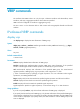
VRRP commands The interfaces that VRRP involves can only be Layer 3 Ethernet interfaces and subinterfaces, VLAN interfaces, and Layer 3 aggregate interfaces unless otherwise specified. VRRP cannot be configured on interfaces in aggregation groups. The term "router" in this document refers to both routers and routing-capable firewalls and firewall modules. IPv4-based VRRP commands display vrrp Use display vrrp to display the state information of VRRP groups.
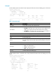
Examples # When VRRP operates in standard mode, display brief information about all VRRP groups on the device. display vrrp IPv4 Standby Information: Run Mode : Standard Run Method : Virtual MAC Total number of virtual routers : 1 Interface VRID State Run Adver Auth Virtual Pri Timer Type IP --------------------------------------------------------------------GE0/1 1 Master 140 1 Simple 1.1.1.
Virtual IP : 1.1.1.1 Virtual MAC : 0000-5e00-0101 Master IP : 1.1.1.2 VRRP Track Information: Track Interface: GE0/2 State : Down Pri Reduced : 10 Track Object State : Positive Pri Reduced : 50 : 1 Table 2 Command output Field Description Run Mode Current VRRP working mode: standard mode. Current VRRP running mode: • Real MAC—Real MAC mode, which means the virtual IP address of the Run Method VRRP group is mapped to the real MAC address of the interface.
Field Description Virtual MAC Virtual MAC address that corresponds to the virtual IP address of the VRRP group. It is displayed only when the router is in master state. Master IP Primary IP address of the interface where the router in master state resides. VRRP Track Information Information about the tracked interface or object. It is displayed only when the vrrp vrid track or vrrp vrid track interface command is executed. Track Interface Interface to be tracked.
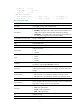
|: Filters command output by specifying a regular expression. For more information about regular expressions, see Getting Started Guide. begin: Displays the first line that matches the specified regular expression and all lines that follow. exclude: Displays all lines that do not match the specified regular expression. include: Displays all lines that match the specified regular expression. regular-expression: Specifies a regular expression, a case-sensitive string of 1 to 256 characters.
Field Description Auth Type Mismatch Number of packets with authentication failures due to mismatching authentication types. Packet Length Errors Number of packets with VRRP packet length errors. Address List Errors Number of packets with virtual IP address list errors. Become Master Number of times that the router worked as the master. Priority Zero Pkts Rcvd Number of received advertisements with the priority of 0. Advertise Rcvd Number of received advertisements.
Related commands display vrrp statistics vrrp method Use vrrp method to specify the type of the MAC addresses mapped to the virtual IP addresses of the VRRP groups. Use undo vrrp method to restore the default. Syntax vrrp method { real-mac | virtual-mac } undo vrrp method Default The virtual MAC addresses are mapped to the virtual IP addresses of the VRRP groups.
Views Interface view Default command level 2: System level Usage guidelines The master of a VRRP group periodically sends VRRP advertisements to indicate its existence. The VRRP advertisements are multicast onto the local network segment and not forwarded by a router, and therefore the packet TTL value will not be changed. When the master of a VRRP group advertises VRRP packets, it sets the packet TTL to 255.
key: Sets the authentication key. This argument is case sensitive. • When md5 authentication applies, it must be a plaintext string of 1 to 8 characters or a ciphertext string of 24 characters if the cipher keyword is not specified, or a ciphertext string of 1 to 41 characters if the cipher keyword is specified.
Parameters virtual-router-id: Virtual router ID or VRRP group number, which ranges from 1 to 255. timer delay delay-value: Sets preemption delay. The delay-value argument ranges from 0 to 255 seconds and defaults to 0 seconds.
The role that a router plays in a VRRP group depends on its priority. A higher priority means that the router is more likely to become the master. Priority 0 is reserved for special use and 255 for the IP address owner. If the router is the IP address owner, its priority is always 255. Therefore, it remains as the master so long as it is functioning correctly. Examples # Set the priority of the router in VRRP group 1 to 150.
[Sysname-GigabitEthernet0/1] vrrp vrid 1 virtual-ip 10.1.1.1 [Sysname-GigabitEthernet0/1] vrrp vrid 1 timer advertise 5 Related commands display vrrp vrrp vrid track Use vrrp vrid track to associate a VRRP group with a track entry and control master switchover in the VRRP group in response to changes (such as uplink state changes) detected by the track entry. Use undo vrrp vrid track to remove the association between a VRRP group and a track entry.
You can create a track entry with the track command before or after you associate it with a VRRP group. For more information about configuring track entries, see High Availability Configuration Guide. Examples # Associate VRRP group 1 on GigabitEthernet 0/1 with track entry 1 and decrease the priority of the device in the VRRP group by 50 when the state of track entry 1 changes to negative. system-view [Sysname] interface gigabitethernet0/1 [Sysname-GigabitEthernet0/1] vrrp vrid 1 virtual-ip 10.
If no interface is specified, the undo vrrp vrid track interface command removes the association between the VRRP group and any interface. If you configure an interface to be tracked on a router that is the IP address owner in a VRRP group, the configuration does not take effect. If the router is not the IP address owner in the VRRP group later, the configuration takes effect.
Usage guidelines The system removes a VRRP group after you delete all the virtual IP addresses in it. The virtual IP address of a VRRP group cannot be 0.0.0.0, 255.255.255.255, loopback address, non A/B/C address and other illegal IP addresses such as 0.0.0.1. A VRRP group operates correctly only when the configured virtual IP address and the interface IP address belong to the same segment and are legal host addresses.
exclude: Displays all lines that do not match the specified regular expression. include: Displays all lines that match the specified regular expression. regular-expression: Specifies a regular expression, a case-sensitive string of 1 to 256 characters. Usage guidelines If you do not specify the verbose keyword, only the brief state information of VRRP groups is displayed. If you specify both an interface and a VRRP group, only the state information of the specified VRRP group on the interface is displayed.
IPv6 Standby Information: Run Mode : Standard Run Method : Virtual MAC Total number of virtual routers : 1 Interface GigabitEtherne0/1 VRID : 1 Adver Timer : 100 Admin Status : Up State : Master Config Pri : 150 Running Pri : 140 Preempt Mode : Yes Delay Time : 10 Auth Type : Simple Key : ****** Virtual IP : FE80::1 Virtual MAC : 0000-5e00-0201 Master IP : FE80::2 VRRP Track Information: Track Interface: GE0/2 State : Down Pri Reduced : 10 Track Object State : Positive Pri
Field Become Master Description Time to wait before the router becomes the master. The unit is milliseconds. Only routers in backup mode have such information. Authentication type: Auth Type • None—No authentication. • Simple—Simple authentication. Key Authentication key. Virtual IP Virtual IPv6 addresses of the VRRP group. Virtual MAC Virtual MAC address that corresponds to the virtual IPv6 address of the VRRP group. It is displayed only when the router is in the state of master.
Default command level 1: Monitor level Parameters interface interface-type interface-number: Displays VRRP group statistics information of the specified interface. The interface-type interface-number argument specifies an interface by its type and number. vrid virtual-router-id: Displays statistics information of the specified VRRP group. The virtual-router-id argument specifies a VRRP group by its group number, which ranges from 1 to 255. |: Filters command output by specifying a regular expression.
Field Description Version Errors Number of packets with version errors. Invalid Type Pkts Rcvd Number of packets with incorrect packet type. Advertisement Interval Errors Number of packets with advertisement interval errors. Hop Limit Errors Number of packets with hop limit errors. Auth Failures Number of packets with authentication failures. Invalid Auth Type Number of packets with authentication failures due to invalid authentication types.
Usage guidelines If you specify both an interface and a VRRP group, the statistics about the specified VRRP group on the specified interface are cleared. If you specify only an interface, the statistics about all the VRRP groups on the interface are cleared. If you specify neither, the statistics about all the VRRP groups on the router are cleared. Examples # Clear the statistics about all the VRRP groups on the router.
vrrp ipv6 vrid authentication-mode Use vrrp ipv6 vrid authentication-mode to configure authentication mode and authentication key for the VRRP groups to send and receive VRRP packets. Use undo vrrp ipv6 vrid authentication-mode to restore the default. Syntax vrrp ipv6 vrid virtual-router-id authentication-mode simple [ cipher ] key undo vrrp ipv6 vrid virtual-router-id authentication-mode Default Authentication is disabled.
vrrp ipv6 vrid preempt-mode Use vrrp ipv6 vrid preempt-mode to configure preemption on the router and configure its preemption delay in a specific VRRP group. Use undo vrrp ipv6 vrid preempt-mode to disable preemption on the router in a specific VRRP group. As a result, the router operates in non-preemptive mode. Use undo vrrp ipv6 vrid preempt-mode timer delay to restore the default preemption delay.
Use undo vrrp ipv6 vrid priority to restore the default. Syntax vrrp ipv6 vrid virtual-router-id priority priority-value undo vrrp ipv6 vrid virtual-router-id priority Default The priority of a router in a VRRP group is 100. Views Interface view Default command level 2: System level Parameters virtual-router-id: VRRP group number, which ranges from 1 to 255. priority-value: Priority value of the router in the specified VRRP group, which ranges from 1 to 254. A higher number indicates a higher priority.
Views Interface view Default command level 2: System level Parameters virtual-router-id: VRRP group number, which ranges from 1 to 255. adver-interval: Interval at which the master in the specified VRRP group sends VRRP advertisements. It ranges from 100 to 4095 centiseconds. Usage guidelines The Adver_Timer controls the interval at which the master sends VRRP packets. Before executing the command, create a VRRP group on an interface and configure the virtual IPv6 address of the VRRP group.
track track-entry-number: Specifies a track entry. The track-entry-number argument ranges from 1 to 1024. reduced priority-reduced: Reduces the priority of the router in the VRRP group by a specific value when the state of the specified track entry changes to the negative state. The priority-reduced argument ranges from 1 to 255. switchover: Enables the router in backup state to take over as the master immediately after the specified track entry changes to the negative state.
Views Interface view Default command level 2: System level Parameters virtual-router-id: VRRP group number, which ranges from 1 to 255. interface interface-type interface-number: Specifies an interface by its type and number. reduced priority-reduced: Value by which the priority decrements. The priority-reduced argument ranges from 1 to 255 and defaults to 10.
vrrp ipv6 vrid virtual-ip Use vrrp ipv6 vrid virtual-ip to create a VRRP group and configure a virtual IPv6 address for it or add another virtual IPv6 address for an existing VRRP group. Use undo vrrp ipv6 vrid virtual-ip to remove an existing VRRP group or the virtual IPv6 address of the VRRP group. Syntax vrrp ipv6 vrid virtual-router-id virtual-ip virtual-address [ link-local ] undo vrrp ipv6 vrid virtual-router-id [ virtual-ip virtual-address [ link-local ] ] Default No VRRP group is created.
Stateful failover commands dhbk configuration-backup Use dhbk configuration-backup to enable the local device to perform automatic configuration synchronization to the peer. Use undo dhbk configuration-backup to restore the default. Syntax dhbk configuration-backup master [ synchronization ] undo dhbk configuration-backup Default A device only receives backup configuration from the peer.
Default Stateful failover is disabled. Views System view Default command level 2: System level Parameters dissymmetric-path: Enables asymmetric-path mode stateful failover. symmetric-path: Enables symmetric-path mode stateful failover. Examples # Enable symmetric-path mode stateful failover. system-view [Sysname] dhbk enable backup-type symmetric-path dhbk ignore-version-check Use dhbk ignore-version-check to disable checking version consistency between the two stateful failover devices.
Syntax dhbk interface interface-list vlan vlan-id undo dhbk interface Default No failover interface or backup VLAN is configured. Views System view Default command level 2: System level Parameters interface-list: Specifies an interface list, represented by { interface-type interface-num }&<1-2>. The interface-type and interface-num arguments refer to the type and number of the failover interface, and the &<1-2> argument indicates that you can specify up to two failover interfaces.
include: Displays all lines that match the specified regular expression. regular-expression: Specifies a regular expression, a case-sensitive string of 1 to 256 characters. Examples # Display the stateful failover status information. display dhbk status Stateful failover: Enabled Backup type: Symmetric path Current state: Independent Current port: GigabitEthernet0/1 VLAN ID: 10 Table 7 Command output Field Description Stateful failover Indicates whether stateful failover is enabled or not.
IPC commands The display commands in this document display only information about active nodes. "Local node" refers to the active MPU. display ipc channel Use display ipc channel to display channel information for a node. Syntax display ipc channel { node node-id | self-node } [ | { begin | exclude | include } regular-expression ] Views Any view Default command level 1: Monitor level Parameters node node-id: Displays channel information for a node.
Table 8 Command output Field Description ChannelID Channel number, which has been predefined and assigned by the system. One channel number corresponds to one module. The display ipc channel command displays the numbers of the current active modules. Description Description information, which is generated by the internal software of the device, describes the functions of a channel. For example, "FIB4" indicates that the channel is used for Layer 3 fast forwarding. "Prehistorical channel, NO.
Table 9 Command output Field Description Dst-NodeID Number of the peer node. Link status: • UP—The connection has been established. • DOWN—The connection has been terminated. LinkStatus display ipc multicast-group Use display ipc multicast-group to display multicast group information for a node.
Field Description ChannelID Channel number. display ipc node Use display ipc node to display node information. Syntax display ipc node [ | { begin | exclude | include } regular-expression ] Views Any view Default command level 1: Monitor level Parameters |: Filters command output by specifying a regular expression. For more information about regular expressions, see Getting Started Guide. begin: Displays the first line that matches the specified regular expression and all lines that follow.
Default command level 1: Monitor level Parameters node node-id: Displays the packet statistics for the specified node. The node-id argument represents the node number, which can be 0 or 1. self-node: Displays packet statistics for the local node. |: Filters command output by specifying a regular expression. For more information about regular expressions, see Getting Started Guide. begin: Displays the first line that matches the specified regular expression and all lines that follow.
Syntax display ipc performance { node node-id | self-node } [ channel channel-id ] [ | { begin | exclude | include } regular-expression ] Views Any view Default command level 1: Monitor level Parameters node node-id: Displays the IPC performance statistics for a node. The node-id argument represents the node number, which can be 0 or 1. self-node: Displays the IPC performance statistics for the local node. channel channel-id: Displays the IPC performance statistics for a channel.
1 1 1 0 78 Table 13 Command output Field Description Peak Peak rate in pps (average rate is computed every 10 seconds, and the greatest average rate is taken as the peak rate). 10Sec Average rate (in pps) for the last 10 seconds. 1Min Average rate (in pps) for the last 1 minute. 5Min Average rate (in pps) for the last 5 minutes. Total-Data Total amount of data collected from the time when IPC performance statistics was enabled to the time when this command is executed.
UNICAST 2 0 4096 0 0 UNICAST 3 0 4096 0 0 UNICAST 0 1 4096 0 0 UNICAST 1 1 4096 0 0 UNICAST 2 1 4096 0 0 UNICAST 3 1 4096 0 0 MULTICAST 0 -- 4096 0 0 MULTICAST 1 -- 4096 0 0 MULTICAST 2 -- 512 0 0 MULTICAST 3 -- 512 0 0 MULTICAST 4 -- 512 0 0 MULTICAST 5 -- 512 0 0 MIXCAST 0 -- 2048 0 0 MIXCAST 1 -- 2048 0 0 Table 14 Command output Field Description Queue type: QueueType • UNICAST—Unicast queue.
Parameters node node-id: Enables IPC performance statistics for a node. The node-id argument represents the node number, which can be 0 or 1. self-node: Enables IPC performance statistics for the local node. channel channel-id: Enables IPC performance statistics for the specified channel, where the channel-id argument represents the channel number in the range of 0 to 255. Usage guidelines When IPC performance statistics is disabled, the statistics data does not change.
Track commands display track Use display track to display track entry information. Syntax display track { track-entry-number | all } [ | { begin | exclude | include } regular-expression ] Views Any view Default command level 1: Monitor level Parameters track-entry-number: Displays information about the specified track entry whose ID is in the range of 1 to 1024. all: Displays information about all the track entries. |: Filters command output by specifying a regular expression.
Remote IP : 192.168.40.1 Local IP : 192.168.40.2 Track ID: 3 Status: Negative Duration: 0 days 0 hours 0 minutes 32 seconds Notification delay: Positive 20, Negative 30 (in seconds) Reference object: Track interface : Interface status : Inserted Interface : GigabitEthernet0/2 Protocol : IPv4 Table 15 Command output Field Description Track ID ID of a track entry. Status of a track entry: Status • Positive—The tracked object functions correctly. • Invalid—The tracked object is invalid.
Field Description Physical status or Layer 3 protocol status of the monitored interface: Protocol • None—Physical status of the monitored interface. • IPv4—IPv4 protocol status of the monitored Layer 3 interface. • IPv6—IPv6 protocol status of the monitored Layer 3 interface.
Usage guidelines After a track entry is created, you cannot change its settings except the delay time. To change the delay time for this track entry, use the track bfd delay command. To modify other settings of this track entry, first delete the entire track entry, and then create a new track entry. When you configure collaboration between Track and BFD, do not configure the virtual IP address of a VRRP group as the local or remote address of a BFD session.
Default No track entry exists. Views System view Default command level 2: System level Parameters track-entry-number: Specifies the track entry ID in the range of 1 to 1024. entry admin-name operation-tag: Specifies the NQA test group to be associated with the track entry. The admin-name argument is the name of the NQA test group administrator who creates the NQA operation, and is a case-insensitive string of 1 to 32 characters.
Syntax track track-entry-number interface interface-type interface-number [ delay { negative negative-time | positive positive-time } * ] undo track track-entry-number Default No track entry exists. Views System view Default command level 2: System level Parameters track-entry-number: Specifies the track entry ID in the range of 1 to 1024. interface-type interface-number: Specifies an interface by its type and number.
track interface protocol Use track interface protocol to create a track entry, associate it with the protocol status of a specific interface, and specify the delay time for the Track module to notify the application modules when the status of the track entry changes. Use undo track to remove the track entry.
Examples # Create track entry 1, and associate it with the IPv4 protocol status of interface GigabitEthernet 0/1.
Collaboration group commands display link-group Use display link-group to display collaboration group information. Syntax display link-group [ number link-group-number | brief ] [ | { begin | exclude | include } regular-expression ] Views Any view Default command level 1: Monitor level Parameters number link-group-number: Specifies a collaboration group by its number in the range of 1 to 24. If this option is not specified, the command displays information about all collaboration groups.
Group Number: 1 Group Status: Up Interface Information: Interface Name Interface Status GigabitEthernet0/1 Up GigabitEthernet0/2 Up # Display brief information about all collaboration groups. display link-group brief Group Number Group Status 1 Up 2 Up Table 16 Command output Field Description Group Number Collaboration group number. Collaboration group state: Group Status • Initial—The collaboration group has no interface. • Up—All interfaces in the collaboration group are up.
Parameters link-group-number: Specifies a collaboration group number in the range of 1 to 24. Usage guidelines An interface can belong to only one collaboration group. A collaboration group can have eight interfaces. Examples # Add GigabitEthernet 0/1 to collaboration group 1.
NQA commands NQA client commands advantage-factor Use advantage-factor to configure the advantage factor that is used to count Mean Opinion Scores (MOS) and Calculated Planning Impairment Factor (ICPIF) values. Use undo advantage-factor to restore the default. Syntax advantage-factor factor undo advantage-factor Default The advantage factor is 0. Views Voice operation view Default command level 2: System level Parameters factor: Specifies the advantage factor in the range of 0 to 20.
Syntax codec-type { g711a | g711u | g729a } undo codec-type Default The codec type for the voice operation is G.711 A-law. Views Voice operation view Default command level 2: System level Parameters g711a: Specifies G.711 A-law codec type. g711u: Specifies G.711 μ-law codec type g729a: Specifies G.729 A-law codec type. Examples # Configure the codec type for the voice operation as g729a.
If the payload length is greater than the string length, the system fills the payload with the string cyclically until the payload is full. For example, if you configure the string as abcd and the payload size as 6 bytes, abcdab is filled. How the string is filled varies with operation types: • For the ICMP echo operation, the string fills the whole payload of ICMP echo requests.
Test type Codec type Default value (in bytes) Voice G.711 A-law 172 Voice G.711 μ-law 172 Voice G.729 A-law 32 Configure the size of the payload in each probe packet correctly. If the traffic amount is large in the network, configure a smaller payload size to reduce network burden. If runt packets are required to be transmitted in the network, configure a bigger payload size to avoid packet loss. Examples # Configure the size of the payload in each ICMP echo request as 80 bytes.
Syntax destination ip ip-address undo destination ip Default No destination IP address is configured for the operation. Views DLSw operation view, FTP operation view, DNS operation view, HTTP operation view, ICMP echo operation view, SNMP operation view, TCP operation view, UDP echo operation view, UDP jitter operation view, voice operation view Default command level 2: System level Parameters ip-address: Specifies the destination IP address of the operation.
Examples # Configure the destination port number of the UDP echo operation as 9000. system-view [Sysname] nqa entry admin test [Sysname-nqa-admin-test] type udp-echo [Sysname-nqa-admin-test-udp-echo] destination port 9000 display nqa history Use display nqa history to display the history records of the specified or all NQA operations.
5 328 Succeeded 2007-04-29 20:54:24.8 4 328 Succeeded 2007-04-29 20:54:24.5 3 328 Succeeded 2007-04-29 20:54:24.1 2 328 Succeeded 2007-04-29 20:54:23.8 1 328 Succeeded 2007-04-29 20:54:23.4 Table 18 Command output Field Description Index History record number. Response Round-trip time if the operation succeeds, timeout time upon timeout, or 0 if the operation cannot be completed (in milliseconds). Status value of test results: Status Time • • • • Succeeded. Unknown error.
regular-expression: Specifies a regular expression, a case-sensitive string of 1 to 256 characters. Usage guidelines If the threshold type is average value, or the monitored performance metric is ICPIF or MOS in the voice operation, the monitoring results are invalid. The monitoring results are accumulated after the NQA operation starts and are not cleared after the operation completes.
Monitored performance metric RTT jitter-DS/jitter-SD Threshold type Collect data in Checked Num Over-threshold Num consecutive Probes after the operation starts. Number of finished probes after the operation starts. Number of probe failures after the operation starts. accumulate Packets sent after the operation starts. Number of packets sent after the operation starts. Number of packets of which the round-trip time exceeds the threshold after the operation starts.
exclude: Displays all lines that do not match the specified regular expression. include: Displays all lines that match the specified regular expression. regular-expression: Specifies a regular expression, a case-sensitive string of 1 to 256 characters. Examples # Display the result of the UDP jitter operation. display nqa result admin test NQA entry (admin admin, tag test) test results: Destination IP address: 192.168.1.
Send operation times: 1000 Receive response times: 0 Min/Max/Average round trip time: 0/0/0 Square-Sum of round trip time: 0 Last succeeded probe time: 0-00-00 00:00:00.
Field Description Packet loss in test Average packet loss ratio. Min positive SD Minimum positive jitter from source to destination. Min positive DS Minimum positive jitter from destination to source. Max positive SD Maximum positive jitter from source to destination. Max positive DS Maximum positive jitter from destination to source. Positive SD number Number of positive jitters from source to destination. Positive DS number Number of positive jitters from destination to source.
Field Description Sum of SD delay Sum of delays from source to destination. Sum of DS delay Sum of delays from destination to source. Square sum of SD delay Square sum of delays from source to destination. Square sum of DS delay Square sum of delays from destination to source. SD lost packet(s) Number of lost packets from the source to the destination. DS lost packet(s) Number of lost packets from the destination to the source.
Examples # Display the statistics of the UDP jitter operation. display nqa statistics admin test NQA entry (admin admin, tag test) test statistics: NO. : 1 Destination IP address: 1.1.1.2 Start time: 2007-01-01 09:33:22.
5 packet-loss accumulate 0 0 6 RTT accumulate 100 52 # Display the statistics of the voice operation. display nqa statistics admin test NQA entry (admin admin, tag test) test statistics: NO. : 1 Destination IP address: 1.1.1.2 Start time: 2007-01-01 09:33:45.
1 ICPIF - - - 2 MOS - - - Table 22 Command output Field Description No. Statistics group number. Destination IP address IP address of the destination. Start time Time when the operation started. Life time Operation duration in seconds. Send operation times Number of probe packets sent. Receive response times Number of response packets received. Min/Max/Average round trip time Minimum/maximum/average round-trip time in milliseconds.
Field Description Min negative DS Minimum absolute value among negative jitters from destination to source. Max negative SD Maximum absolute value among negative jitters from source to destination. Max negative DS Maximum absolute value among negative jitters from destination to source. Negative SD number Number of negative jitters from source to destination. Negative DS number Number of negative jitters from destination to source.
Field Description Over-threshold Num Number of threshold violations. Table 23 Description of the threshold monitoring fields Threshold type Collect data in Checked Num Over-threshold Num accumulate Probes in the counting interval. Number of finished probes in the counting interval. Number of probes of which the duration exceeds the threshold in the counting interval. average N/A N/A N/A consecutive Probes in the counting interval. Number of finished probes in the counting interval.
Use undo filename to restore the default. Syntax filename filename undo filename Default No file is specified. Views FTP operation view Default command level 2: System level Parameters filename: Specifies the name of a file, a case-sensitive string of 1 to 200 characters. Examples # Specify the file to be transferred between the FTP server and the FTP client as config.txt.
Examples # Configure the ICMP echo operation to repeat at an interval of 1000 milliseconds. system-view [Sysname] nqa entry admin test [Sysname-nqa-admin-test] type icmp-echo [Sysname-nqa-admin-test-icmp-echo] frequency 1000 history-record enable Use history-record enable to enable the saving of history records of an NQA operation. Use undo history-record enable to disable the history records saving function.
Default The history records in an NQA operation are kept for 120 minutes. Views Any NQA operation view Default command level 2: System level Parameters keep-time: Specifies how long the history records can be saved. The value range for the time is 1 to 1440 minutes. Usage guidelines When an NQA operation completes, the timer starts. All records are removed when the lifetime is reached. Examples # Configure the lifetime of the history records in an NQA operation as 100 minutes.
Examples # Configure the maximum number of history records that can be saved in an NQA operation as 10. system-view [Sysname] nqa entry admin test [Sysname-nqa-admin-test] type icmp-echo [Sysname-nqa-admin-test-icmp-echo] history-record number 10 http-version Use http-version to specify the HTTP version used in the HTTP operation. Use undo http-version to restore the default. Syntax http-version v1.0 undo http-version Default HTTP 1.0 is used in the HTTP operation.
Default command level 2: System level Parameters active: Sets the data transmission mode to active for the FTP operation. In this mode, the FTP server initiates a connection request. passive: Sets the data transmission mode to passive for the FTP operation. In this mode, the FTP client initiates a connection request. Examples # Set the data transmission mode to passive for the FTP operation.
nqa Use nqa to create an NQA operation and enter NQA operation view. Use undo nqa to remove the operation. Syntax nqa entry admin-name operation-tag undo nqa { all | entry admin-name operation-tag } Default No NQA operation is created. Views System view Default command level 2: System level Parameters admin-name: Specifies the name of the administrator creating the NQA operation, a case-insensitive string of 1 to 32 characters excluding hyphens (-).
Views System view Default command level 2: System level Examples # Enable the NQA client. system-view [Sysname] nqa agent enable Related commands nqa server enable nqa agent max-concurrent Use nqa agent max-concurrent to configure the maximum number of operations that the NQA client can simultaneously perform. Use undo nqa agent max-concurrent to restore the default.
undo nqa schedule admin-name operation-tag Views System view Default command level 2: System level Parameters admin-name: Specifies the administrator name, a case-insensitive string of 1 to 32 characters. operation-tag: Specifies the operation tag, a case-insensitive string of 1 to 32 characters. start-time: Specifies the start time and date of the NQA operation. hh:mm:ss: Specifies the start time of an NQA operation. yyyy/mm/dd: Specifies the start date of an NQA operation.
Views FTP operation view Default command level 2: System level Parameters get: Gets a file from the FTP server. put: Transfers a file to the FTP server. Usage guidelines When you execute the put command, the NQA client creates a file named file-name of fixed size on the FTP server. The file-name argument does not represent any file on the NQA client. When you execute the get command, the client does not save the file obtained from the FTP server.
operation interface Use operation interface to specify the interface to perform the DHCP operation. The specified interface must be up. Otherwise, no probe packets can be sent out. Use undo operation interface to restore the default. Syntax operation interface interface-type interface-number undo operation interface Default No interface is specified to perform the DHCP operation.
Default command level 2: System level Parameters cipher: Sets a ciphertext password. simple: Sets a plaintext password. password: Specifies the password used to log in to the FTP server. This argument is case sensitive. If simple is specified, it must be a plaintext string of 1 to 32 characters. If cipher is specified, it must be a ciphertext string of 1 to 73 characters. If neither cipher nor simple is specified, you set a plaintext password.
Examples # Configure the ICMP echo operation to perform 10 probes. system-view [Sysname] nqa entry admin test [Sysname-nqa-admin-test] type icmp-echo [Sysname-nqa-admin-test-icmp-echo] probe count 10 probe packet-interval Use probe packet-interval to configure the interval for sending packets in the probe. Use undo probe packet-interval to restore the default. Syntax probe packet-interval packet-interval undo probe packet-interval Default The interval is 20 milliseconds.
Default command level 2: System level Parameters packet-number: Specifies the number of packets to be sent per probe. The value range for the UDP jitter operation is 10 to 1000 and for the voice operation is 10 to 60000. Examples # Configure the UDP jitter probe to send 100 packets.
Use undo probe timeout to restore the default. Syntax probe timeout timeout undo probe timeout Default The timeout time of a probe is 3000 milliseconds. Views DHCP operation view, DNS operation view, DLSw operation view, FTP operation view, HTTP operation view, ICMP echo operation view, SNMP operation view, TCP operation view, UDP echo operation view Default command level 2: System level Parameters timeout: Specifies the probe timeout time in milliseconds.
Parameters item-number: Specifies a reaction entry ID in the range of 1 to 10. threshold-value: Specifies threshold values. upper-threshold: Specifies the upper threshold in the range of 1 to 100. lower-threshold: Specifies the lower threshold in the range of 1 to 100. It must not be greater than the upper threshold. action-type: Specifies what action to be triggered and it defaults to none. none: Specifies the action of only displaying results on the terminal display.
jitter-ds: Specifies the destination-to-source jitter of each probe packet as the monitored element (or performance metric). jitter-sd: Specifies source-to-destination jitter of each probe packet as the monitored element. threshold-type: Specifies a threshold type. accumulate accumulate-occurrences: Specifies the maximum number of threshold violations in the operation. The value range for the UDP jitter operation is 1 to 14999 and for the voice operation is 1 to 59999.
reaction checked-element mos Use reaction checked-element mos to configure a reaction entry for monitoring the MOS value in the NQA operation. You cannot edit a reaction entry. To change the attributes in a reaction entry, use undo reaction to delete the entry first and then configure a new one. Use undo reaction to delete the specified reaction entry.
reaction checked-element { owd-ds | owd-sd } Use reaction checked-element { owd-ds | owd-sd } to configure a reaction entry for monitoring the one-way delay. You cannot edit a reaction entry. To change the attributes in a reaction entry, use undo reaction to delete the entry first and then configure a new one. Use undo reaction to delete the specified reaction entry.
reaction checked-element packet-loss Use reaction checked-element packet-loss to configure a reaction entry for monitoring packet loss in the NQA operation. You cannot edit a reaction entry. To change the attributes in a reaction entry, use undo reaction to delete the entry first and then configure a new one. Use undo reaction to delete the specified reaction entry.
Use undo reaction to delete the specified reaction entry. Syntax reaction item-number checked-element probe-duration threshold-type { accumulate accumulate-occurrences | average | consecutive consecutive-occurrences } threshold-value upper-threshold lower-threshold [ action-type { none | trap-only } ] undo reaction item-number Default No reaction entry for monitoring the probe duration is configured.
[Sysname-nqa-admin-test] type icmp-echo [Sysname-nqa-admin-test-icmp-echo] reaction 1 checked-element probe-duration threshold-type average threshold-value 50 5 action-type trap-only # Create reaction entry 2 for monitoring the duration of ICMP echo operation. Set the upper threshold to 50 milliseconds, and the lower threshold to 5 milliseconds. Before the NQA operation starts, the initial state of the reaction entry is invalid.
Parameters item-number: Specifies a reaction entry ID in the range of 1 to 10. threshold-type: Specifies a threshold type. accumulate accumulate-occurrences: Specifies the maximum number of probe failures, in the range of 1 to 15. consecutive consecutive-occurrences: Specifies the maximum number of consecutive probe failures, in the range of 1 to 16. action-type: Specifies what action to be triggered. The default action is none. none: Specifies the action of only displaying results on the terminal display.
Default No reaction entries are configured. Views DHCP operation view, DNS operation view, DLSw operation view, FTP operation view, HTTP operation view, ICMP echo operation view, SNMP operation view, TCP operation view, UDP echo operation view Default command level 2: System level Parameters item-number: Specifies a reaction entry ID in the range of 1 to 10. threshold-type: Specifies a threshold type.
Views UDP jitter operation view, voice operation view Default command level 2: System level Parameters item-number: Specifies a reaction entry ID in the range of 1 to 10. threshold-type: Specifies a threshold type. accumulate accumulate-occurrences: Specifies the total number of threshold violations. The value range for UDP jitter operation is 1 to 15000 and for voice operation is 1 to 60000. average: Specifies to check the packet average round-trip time.
reaction trap Use reaction trap to configure the sending of traps to the NMS under specified conditions. Use undo reaction trap to restore the default. Syntax reaction trap { probe-failure cumulate-probe-failures } consecutive-probe-failures | test-complete | test-failure undo reaction trap { probe-failure | test-complete | test-failure } Default No traps are sent to the NMS.
Default No domain name is configured. Views DNS operation view Default command level 2: System level Parameters domain-name: Specifies the domain name to be resolved. It is a case-insensitive string separated by dots (.), each part consisting of 1 to 63 characters. The total length must be within 255 characters. Valid characters in a part include letters, digits, hyphens (-), and underscores (_). Examples # Set the domain name domain1 to be resolved.
[Sysname-nqa-admin-test-icmp-echo] route-option bypass-route source interface Use source interface to configure the source interface for ICMP echo request packets. The ICMP echo request packets take the primary IP address of the source interface as their source IP address when no source IP address is specified. The specified source interface must be up. Otherwise, no ICMP echo requests can be sent out. Use undo source interface to restore the default.
Syntax source ip ip-address undo source ip Default No source IP address is configured for probe packets. Views DLSw operation view, FTP operation view, HTTP operation view, ICMP echo operation view, SNMP operation view, TCP operation view, UDP echo operation view, UDP jitter operation view, voice operation view Default command level 2: System level Parameters ip-address: Specifies the source IP address of the operation.
Parameters port-number: Specifies the source port number of probe packets, in the range of 1 to 50000. Examples # Configure port 8000 as the source port of probe packets in the UDP echo operation. system-view [Sysname] nqa entry admin test [Sysname-nqa-admin-test] type udp-echo [Sysname-nqa-admin-test-udp-echo] source port 8000 statistics hold-time Use statistics hold-time to configure the hold time of statistics groups for an NQA operation.
Syntax statistics max-group number undo statistics max-group Default A maximum of two statistics groups can be saved. Views DLSw operation view, DNS operation view, FTP operation view, HTTP operation view, ICMP echo operation view, SNMP operation view, TCP operation view, UDP echo operation view, UDP jitter operation view, voice operation view Default command level 2: System level Parameters number: Specifies the maximum number of statistics groups that can be saved, in the range of 0 to 100.
Parameters interval: Specifies the interval in minutes for collecting statistics for an NQA operation, in the range of 1 to 35791394. Usage guidelines NQA collects the result statistics within the specified interval in a statistics group. The statistics form a statistics group. To view information about the statistics groups, use the display nqa statistics command. This command is not available for the DHCP operation.
Use undo ttl to restore the default. Syntax ttl value undo ttl Default The TTL for probe packets is 20. Views DLSw operation view, DNS operation view, FTP operation view, HTTP operation view, ICMP echo operation view, SNMP operation view, TCP operation view, UDP echo operation view, UDP jitter operation view, voice operation view Default command level 2: System level Parameters value: Specifies the TTL for probe packets, in the range of 1 to 255.
ftp: Specifies the FTP operation type. http: Specifies the HTTP operation type. icmp-echo: Specifies the ICMP echo operation type. snmp: Specifies the SNMP operation type. tcp: Specifies the TCP operation type. udp-echo: Specifies the UDP echo operation type. udp-jitter: Specifies the UDP jitter operation type. voice: Specifies the voice operation type. Examples # Specify the type of the NQA operation as FTP and enter FTP operation view.
Use undo username to remove the username. Syntax username username undo username Default No username is configured for logging in to the FTP server. Views FTP operation view Default command level 2: System level Parameters username: Specifies the username used to log in to the FTP server. The username is a case-sensitive string of 1 to 32 characters. Examples # Configure the login username as administrator.
Examples # Specify vpn1 as the VPN. system-view [Sysname] nqa entry admin test [Sysname-nqa-admin-test] type icmp-echo [Sysname-nqa-admin-test-icmp-echo] vpn-instance vpn1 NQA server commands NOTE: You only need to configure the NQA server for UDP jitter, TCP, UDP echo, and voice operations. display nqa server status Use display nqa server status to display NQA server status.
Table 24 Command output Field Description tcp-connect TCP connect listening service. udp-echo UDP echo listening service. IP Address IP address specified for the TCP/UDP listening service on the NQA server. Port Port number of the TCP/UDP listening service on the NQA server. Listening service status: Status • active—Listening service is ready. • inactive—Listening service is not ready. nqa server enable Use nqa server enable to enable the NQA server.
Syntax nqa server tcp-connect ip-address port-number undo nqa server tcp-connect ip-address port-number Views System view Default command level 2: System level Parameters ip-address: Specifies the IP address for the TCP connect listening service. port-number: Specifies the port number for the TCP connect listening service, in the range of 1 to 50000. Usage guidelines Configure the command on the NQA server for the TCP operation only.
Usage guidelines Configure the command on the NQA server for the UDP jitter, UDP echo, and voice operations only. The IP address and port number must be consistent with those configured on the NQA client and must be different from those of an existing UDP listening service. The IP address must be that of an interface on the NQA server. Otherwise, the configuration becomes invalid. Examples # Configure a UDP listening service to enable the NQA server to listen and respond on the IP address 169.254.10.
Ethernet link aggregation commands The device does not support the dynamic aggregation mode. default Use default to restore the default settings for an aggregate interface or subinterface. Syntax default Views Layer 2 aggregate interface view, Layer 2 aggregate subinterface view, Layer 3 aggregate interface view, Layer 3 aggregate subinterface view Default command level 2: System level Usage guidelines CAUTION: The default command might interrupt ongoing network services.
Default The description of an interface is interface-name Interface. For example, the default description of Bridge-Aggregation1 is Bridge-Aggregation1 Interface. Views Layer 2 aggregate interface view, Layer 2 aggregate subinterface view, Layer 3 aggregate interface view, Layer 3 aggregate subinterface view Default command level 2: System level Parameters text: Specifies the interface description, a string of 1 to 80 characters.
exclude: Displays all lines that do not match the specified regular expression. include: Displays all lines that match the specified regular expression. regular-expression: Specifies a regular expression, a case-sensitive string of 1 to 256 characters. Usage guidelines If bridge-aggregation | route-aggregation is not specified, this command displays information about all interfaces.
Link: ADM - administratively down; Stby - standby Speed or Duplex: (a)/A - auto; H - half; F - full Type: A - access; T - trunk; H - hybrid Interface Link Speed Duplex Type PVID Description BAGG1 DOWN auto A A 1 # Display brief information about Layer 3 aggregate interface Route-Aggregation 1.
Field Description IP packet processing. Internet protocol processing Disabled indicates that IP packets cannot be processed. For an interface configured with an IP address, this field changes to Internet Address is. Output queue : (Urgent queuing : Size/Length/Discards) Output queue (current message number in the urgent queue/ maximum number of messages allowed in the urgent queue/number of discarded messages).
Syntax display lacp system-id [ | { begin | exclude | include } regular-expression ] Views Any view Default command level 1: Monitor level Parameters |: Filters command output by specifying a regular expression. For more information about regular expressions, see Getting Started Guide. begin: Displays the first line that matches the specified regular expression and all lines that follow. exclude: Displays all lines that do not match the specified regular expression.
Default command level 1: Monitor level Parameters bridge-aggregation: Displays the load sharing criteria of the aggregation group corresponding to the specified Layer 2 aggregate interface. route-aggregation: Displays the load sharing criteria of the aggregation group corresponding to the specified Layer 3 aggregate interface. interface-number: Specifies an existing aggregate interface number. The value range for this argument is 1 to 1024. |: Filters command output by specifying a regular expression.
destination-port, source-port, ip-protocol Layer 3 traffic: destination-ip address, destination-port, source-ip address, source-port, ip-protocol # Display the configured link-aggregation load sharing criteria of the aggregation group corresponding to Layer 2 aggregate interface Bridge-Aggregation 10.
Syntax display link-aggregation member-port [ interface-list ] [ | { begin | exclude | include } regular-expression ] Views Any view Default command level 1: Monitor level Parameters interface-list: Specifies a list of link aggregation member ports, in the format interface-type interface-number1 [ to interface-type interface-number2 ], where interface-type interface-number specifies an interface by its type and number. |: Filters command output by specifying a regular expression.
Aggregation Interface: Bridge-Aggregation10 Local: Port Number: 2 Port Priority: 32768 Oper-Key: 2 Flag: {ACDEF} Remote: System ID: 0x8000, 000f-e267-6c6a Port Number: 26 Port Priority: 32768 Oper-Key: 2 Flag: {ACDEF} Received LACP Packets: 5 packet(s) Illegal: 0 packet(s) Sent LACP Packets: 7 packet(s) Table 28 Command output Field Description LACP state flags: Flags • • • • • • • • A—LACP is enabled. B—LACP short timeout. C—The sending system detects that the link is aggregatable.
Syntax display link-aggregation summary [ | { begin | exclude | include } regular-expression ] Views Any view Default command level 1: Monitor level Parameters |: Filters command output by specifying a regular expression. For more information about regular expressions, see Getting Started Guide. begin: Displays the first line that matches the specified regular expression and all lines that follow. exclude: Displays all lines that do not match the specified regular expression.
Field Description Load-sharing type: Loadsharing Type • Shar—Load sharing. • NonS—Non-load sharing. Actor System ID Local system ID, which comprises the system LACP priority and the system MAC address. AGG Interface Type and number of the aggregate interface. AGG Mode Aggregation group type. Partner ID System ID of the partner, which comprises the system LACP priority and the system MAC address. Select Ports Total number of Selected ports. Unselect Ports Total number of Unselected ports.
Usage guidelines To display the information about a specific Layer 2 or Layer 3 aggregation group, use the display link-aggregation verbose bridge-aggregation interface-number or display link-aggregation verbose route-aggregation interface-number command. To display the information about all Layer 2 or Layer 3 aggregation groups, use the display link-aggregation verbose bridge-aggregation or display link-aggregation verbose route-aggregation command.
Aggregation Interface: Bridge-Aggregation20 Aggregation Mode: Static Loadsharing Type: NonS Port Status Priority Oper-Key -------------------------------------------------------------------------------GE0/1 U 32768 1 GE0/2 U 32768 1 GE0/3 U 63 1 Table 30 Command output Field Description Load sharing type: Loadsharing Type • Shar—Load sharing. • NonS—Non-load sharing. Port Status Port state: Selected or Unselected.
enable snmp trap updown Use enable snmp trap updown to enable linkUp/linkDown trap generation for the aggregate interface. Use undo enable snmp trap updown to disable linkUp/linkDown trap generation for the aggregate interface. Syntax enable snmp trap updown undo enable snmp trap updown Default LinkUp/linkDown trap generation is enabled for an aggregate interface.
Parameters interface-number: Specifies a Layer 2 aggregate interface number. The value range for this argument is 1 to 1024. interface-number.subnumber: Specifies a subinterface of a Layer 2 aggregate interface. The interface-number argument specifies the main interface number. The subnumber argument specifies the subinterface number and is separated from the main interface number by a dot (.). The value ranges for the interface-number argument and the subnumber argument are both 1 to 4094.
Removing a Layer 3 aggregate subinterface does not affect the state of the main interface and the corresponding aggregation group. Examples # Create Layer 3 aggregate interface Route-Aggregation 1 and enter its view. system-view [Sysname] interface route-aggregation 1 [Sysname-Route-Aggregation1] lacp period short Use lacp period short to set the LACP timeout interval on a port to the short timeout interval (1 second). Use undo lacp period to restore the default setting.
Parameters system-priority: Specifies the LACP priority of the local system, in the range of 0 to 65535. The smaller the value, the higher the system LACP priority. Examples # Set the system LACP priority to 64. system-view [Sysname] lacp system-priority 64 link-aggregation load-sharing mode Use link-aggregation load-sharing mode to configure the global or group-specific link-aggregation load sharing criteria. Use undo link-aggregation load-sharing mode to restore the default setting.
source-port: Performs load sharing in link aggregation groups based on source port. Usage guidelines The load sharing criteria that you configure will overwrite the previous criteria. If unsupported load sharing criteria are configured, an error prompt will appear. Examples # Configure the source IP address and destination IP address as the global link-aggregation load sharing criteria.
link-aggregation port-priority Use link-aggregation port-priority to set the aggregation priority of a port. Use undo link-aggregation port-priority to restore the default setting. Syntax link-aggregation port-priority port-priority undo link-aggregation port-priority Default The aggregation priority of a port is 32768. Views Ethernet interface view Default command level 2: System level Parameters port-priority: Specifies a port aggregation priority in the range of 0 to 65535.
Default command level 2: System level Parameters number: Specifies the maximum number of Selected ports allowed in an aggregation group.
Default command level 2: System level Parameters number: Specifies the minimum number of Selected ports in an aggregation group required to bring up the aggregate interface.
Parameters size: Specifies the MTU in bytes. The value range for this argument is 46 to 1500. Examples # Set the MTU of Layer 3 aggregate interface Route-Aggregation 1 to 1430 bytes. system-view [Sysname] interface route-aggregation 1 [Sysname-Route-Aggregation1] mtu 1430 Related commands display interface port link-aggregation group Use port link-aggregation group to assign the Ethernet interface to the specified aggregation group.
reset counters interface Use reset counters interface to clear the statistics of the specified aggregate interface or interfaces. Syntax reset counters interface [ { bridge-aggregation | route-aggregation } [ interface-number ] ] Views User view Default command level 2: System level Parameters bridge-aggregation: Clears statistics for Layer 2 aggregate interfaces. route-aggregation: Clears statistics for Layer 3 aggregate interfaces. interface-number: Specifies an aggregate interface number.
Parameters interface-list: Specifies a list of link aggregation member ports, in the format interface-type interface-number1 [ to interface-type interface-number2 ], where interface-type interface-number specifies an interface by its type and number. Examples # Clear the LACP statistics on all link aggregation member ports. reset lacp statistics Related commands display link-aggregation member-port shutdown Use shutdown to shut down the aggregate interface or subinterface.
Interface backup commands The following matrix shows the feature and hardware compatibility: Hardware Compatibility F1000-A-EI/F1000-S-EI Yes F1000-E Yes F5000 Yes F5000-S/F5000-C Yes VPN firewall modules Yes 20-Gbps VPN firewall modules No display standby flow Use display standby flow to display statistics about traffic on the active interfaces participating in load balancing.
BandWidth(b/s) : 9000 UsedBandWidth(b/s) : 8000 Table 31 Command output Field Description Interfacename Name of the active interface. Flow-interval(s) Intervals for checking traffic on the active interface. LastInOctets Sum of the octets received on the active interface until the last check. LastOutOctets Sum of the octets sent on the active interface until the last check. InFlow(Octets) Sum of the octets received on the active interface during the last interval.
M---MAIN B---BACKUP D---LOAD P---PULLED V---MOVED U---USED The following tables describe the meanings of each state. Table 32 States of active and standby interfaces State Active interface Standby interface UP The physical link is functioning correctly for data transmission. DOWN The physical link is not available for data transmission, for example, because no cable connection is present. STANDBY N/A The state of the standby interfaces when the active interface is functioning.
Flag Description P---PULLED The interface board where the interface is located is removed. Table 36 Load balancing states State Description WAKE The active interface is transiting from the working state to the non-working state. The standby interface is working in the load balancing state to transmit data together with the active interface.
system-view [Sysname] interface gigabitethernet 0/1 [Sysname-GigabitEthernet0/1] standby bandwidth 10000 Related commands standby interface standby interface Use standby interface to specify a standby interface for the current interface. Use undo standby interface to remove the specified standby interface. Syntax standby interface interface-type interface-number [ priority ] undo standby interface interface-type interface-number Default No standby interface is specified.
Syntax standby threshold enable-threshold disable-threshold undo standby threshold Default Load balancing threshold is disabled. Views Interface view Default command level 2: System level Parameters enable-threshold: Specifies the upper load balancing threshold. It indicates the percentage of the available active-interface bandwidth that the traffic load must exceed for the standby interface to come up for load balancing. The value for this argument is in the range of 1 to 99.
standby timer delay Use standby timer delay to set switchover delays on the interface. Use undo standby timer delay to restore the default. Syntax standby timer delay enable-delay disable-delay undo standby timer delay Default Switchover delays on the active and standby interfaces are 0, indicating immediate switchover without any delay. Views Interface view Default command level 2: System level Parameters enable-delay: Specifies switchover delay from the active interface to the standby interface.
Default The interval for checking the traffic size on the active interface is 30 seconds. Views Interface view Default command level 2: System level Parameters interval: Specifies flow check interval in the range of 30 to 600 seconds. Usage guidelines Use this command after standby interfaces are specified. Examples # Configure load balancing, backup bandwidth and flow check interval on interface GigabitEthernet 0/1 as 60 seconds.
Examples # Set the delay timer for the backup function to take effect on system startup to 40 seconds. system-view [Sysname] standby timer startup 40 standby track Use standby track to associate an interface with a track entry. Use undo standby track to remove the association. Syntax standby track track-entry-number undo standby track Default An interface is not associated with a track entry.
BFD commands The following matrix shows the feature and hardware compatibility: Hardware Compatibility F1000-A-EI/F1000-S-EI No F1000-E No F5000 Yes F5000-S/F5000-C No VPN firewall modules No 20-Gbps VPN firewall modules No bfd authentication-mode Use bfd authentication-mode to configure the BFD authentication mode on the interface. Use undo bfd authentication-mode to restore the default.
password: Sets the password for simple authentication. This argument is case sensitive. It must be a plaintext string of 1 to 16 characters or a ciphertext string of 33 to 53 characters. Usage guidelines For security purposes, all passwords, including passwords configured in plain text, are saved in cipher text. The authentication mode, key-id, key (or password) used by both ends trying to establish a BFD session must be the same.
Syntax bfd echo-source-ip ip-address undo bfd echo-source-ip Views System view Default command level 2: System level Parameters ip-address: Source IP address of BFD echo packets. Usage guidelines Do not configure the source IP address of the BFD echo packets to belong to the same network segment as any interface address of the device. Otherwise, a large amount of ICMP redirect packets might be sent by the remote device, causing network congestion.
bfd min-receive-interval Use bfd min-receive-interval to configure the minimum interval for receiving BFD control packets. Use undo bfd min-receive-interval to restore the default minimum interval for receiving BFD control packets. Syntax bfd min-receive-interval value undo bfd min-receive-interval Views Interface view Default command level 2: System level Parameters value: Minimum interval for receiving BFD control packets, in milliseconds. The value must be a multiple of 10.
Parameters value: Minimum interval for transmitting BFD control packets, in milliseconds. The value must be a multiple of 10. Usage guidelines A proper interval ensures that BFD control packets are not transmitted faster than the device can deal with.
Syntax bfd session init-mode { active | passive } undo bfd session init-mode Default BFD uses the active mode. Views System view Default command level 2: System level Parameters active: Uses the active mode. In the active mode, BFD actively transmits BFD control packets to the remote device. passive: Uses the passive mode.
BFD Error debugging is on BFD Event debugging is on BFD FSM debugging is on BFD Packet Receive debugging is on BFD Packet Send debugging is on BFD SCM debugging is on BFD Timer debugging is on display bfd interface Use display bfd interface to display information about BFD-enabled interfaces. Syntax display bfd interface [ verbose ] [ | { begin | exclude | include } regular-expression ] Views Any view Default command level 1: Monitor level Parameters verbose: Displays detailed interface information.
Auth mode: Simple LD/RD SourceAddr DestAddr ConnType State Mode 2/2 192.168.11.11 192.168.11.10 Direct Up Ctrl Table 37 Command output Field Description Interface Interface name. Session Num Number of sessions established on the local interface. Min Trans Inter Minimum control packet transmit interval configured on the interface. Min Recv Inter Minimum control packet receive interval configured on the interface. DetectMult Detection time multiplier.
Examples # Display detailed BFD session information on the device. display bfd session verbose Total session number: 1 Up session number: 1 Init mode: Active IPv4 session working under Ctrl mode: Local Discr: 1 Source IP: 111.1.1.1 Remote Discr: 1 Destination IP: 111.1.1.
Field Description Running up for Time interval for which the session has been up. Chassis/Board Num Chassis/card maintaining the session. Protocol Registered protocol. Diag Info Diagnostic information about the session. reset bfd session statistics Use reset bfd session statistics to clear the BFD session statistics. Syntax reset bfd session statistics Views User view Default command level 1: Monitor level Parameters None Examples # Clear statistics about all the BFD sessions.
Support and other resources Contacting HP For worldwide technical support information, see the HP support website: http://www.hp.
Conventions This section describes the conventions used in this documentation set. Command conventions Convention Description Boldface Bold text represents commands and keywords that you enter literally as shown. Italic Italic text represents arguments that you replace with actual values. [] Square brackets enclose syntax choices (keywords or arguments) that are optional. { x | y | ... } Braces enclose a set of required syntax choices separated by vertical bars, from which you select one.
Network topology icons Represents a generic network device, such as a router, switch, or firewall. Represents a routing-capable device, such as a router or Layer 3 switch. Represents a generic switch, such as a Layer 2 or Layer 3 switch, or a router that supports Layer 2 forwarding and other Layer 2 features. Represents a security product, such as a firewall, a UTM, or a load-balancing or security card that is installed in a device.
Index ABCDEFHILMNOPRSTUVW display ipc queue,39 A display lacp system-id,113 advantage-factor,53 display link-aggregation load-sharing mode,114 B display link-aggregation member-port,116 bfd authentication-mode,143 display link-aggregation summary,118 bfd detect-multiplier,144 display link-aggregation verbose,120 bfd echo-source-ip,144 display link-group,50 bfd min-echo-receive-interval,145 display nqa history,58 bfd min-receive-interval,146 display nqa reaction counters,59 bfd min-transmit-
lacp system-priority,125 reset bfd session statistics,152 link-aggregation load-sharing mode,126 reset counters interface,132 link-aggregation mode,127 reset ipc performance,41 link-aggregation port-priority,128 reset lacp statistics,132 link-aggregation selected-port maximum,128 reset vrrp ipv6 statistics,20 link-aggregation selected-port minimum,129 reset vrrp statistics,6 link-group,51 resolve-target,95 M route-option bypass-route,96 mode,74 S mtu,130 shutdown,133 snmp-agent trap enabl
vrrp ipv6 vrid track,25 vrrp vrid timer advertise,11 vrrp ipv6 vrid track interface,26 vrrp vrid track,12 vrrp ipv6 vrid virtual-ip,28 vrrp vrid track interface,13 vrrp method,7 vrrp vrid virtual-ip,14 vrrp un-check ttl,7 W vrrp vrid authentication-mode,8 Websites,153 vrrp vrid preempt-mode,9 vrrp vrid priority,10 158