HP VPN Firewall Appliances High Availability Configuration Guide Part number: 5998-4169 Software version: F1000-A-EI/F1000-S-EI (Feature 3726) F1000-E (Release 3177) F5000 (Feature 3211) F5000-S/F5000-C (Release 3808) VPN firewall modules (Release 3177) 20-Gbps VPN firewall modules (Release 3817) Document version: 6PW101-20130923
Legal and notice information © Copyright 2013 Hewlett-Packard Development Company, L.P. No part of this documentation may be reproduced or transmitted in any form or by any means without prior written consent of Hewlett-Packard Development Company, L.P. The information contained herein is subject to change without notice.
Contents High availability overview··········································································································································· 1 Availability requirements ·················································································································································· 1 Availability evaluation ········································································································································
Configuration guidelines ··············································································································································· 53 Configuring stateful failover in the Web interface ····································································································· 54 Configuring stateful failover ································································································································· 54 Stateful failover con
Configuring NQA ··················································································································································· 100 Overview······································································································································································· 100 Collaboration ······················································································································································
Configuring load sharing criteria for link aggregation groups ······································································ 160 Displaying and maintaining Ethernet link aggregation··················································································· 161 Ethernet link aggregation configuration examples ·························································································· 162 Configuring interface backup ·····························································
Server load balancing configuration example ································································································· 228 Firewall load balancing configuration example ······························································································ 232 Outbound link load balancing configuration example ··················································································· 236 Inbound link load balancing configuration example ································
High availability overview Because communication interruptions can seriously affect widely-deployed value-added services such as IPTV and video conference, basic network infrastructures must be able to provide high availability. The following are the effective ways to improve availability: • Increasing fault tolerance. • Speeding up fault recovery. • Reducing impact of faults on services.
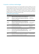
MTTR = fault detection time + hardware replacement time + system initialization time + link recovery time + routing time + forwarding recovery time. A smaller value of each item means a smaller MTTR and a higher availability. High availability technologies Increasing MTBF or decreasing MTTR can enhance the availability of a network. The high availability technologies described in this section meet the level 2 and level 3 high availability requirements in the aspect of decreasing MTTR.
Protection switchover technologies Protection switchover technologies aim at recovering network faults. They back up hardware, link, routing, and service information for switchover in case of network faults to ensure continuity of network services. A single availability technology cannot solve all problems. You should use a combination of availability technologies, chosen on the basis of detailed analysis of network environments and user requirements, to enhance network availability.
Configuring VRRP The interfaces that VRRP involves can be only Layer 3 Ethernet interfaces and subinterfaces, VLAN interfaces, and Layer 3 aggregate interfaces unless otherwise specified. VRRP cannot be configured on an interface of an aggregation group. The term "router" in this document refers to both routers and routing-capable firewalls and firewall modules. VRRP overview As shown in Figure 1, you can typically configure a default route with the gateway as the next hop for every host on a LAN.
VRRP standard mode VRRP group VRRP combines a group of routers (including a master and multiple backups) on a LAN into a virtual router called VRRP group. A VRRP group has the following features: • A virtual router has a virtual IP address. A host on the LAN only needs to know the IP address of the virtual router and uses the IP address as the next hop of the default route. • Every host on the LAN communicates with external networks through the virtual router.
the IP address owner. The router acting as the IP address owner in a VRRP group always has the running priority 255 and acts as the master as long as it works correctly. 2. Working mode A router in a VRRP group operates in either of the following modes: { { 3. Non-preemptive mode—When a router in the VRRP group becomes the master, it stays as the master as long as it operates correctly, even if a backup is assigned a higher priority later.
Figure 3 VRRPv2 packet format Figure 4 VRRPv3 packet format 0 3 Version Auth Type 7 Type 15 23 Virtual Rtr ID Priority Adver Int 31 Count IPv6 Addrs Checksum IPv6 address 1 ... IPv6 address n Authentication data 1 Authentication data 2 A VRRP packet comprises the following fields: • Version—Version number of the protocol, 2 for VRRPv2 and 3 for VRRPv3. • Type—Type of the VRRPv2 or VRRPv3 packet. It must be VRRP advertisement, represented by 1.
• IP Address/IPv6 Address—Virtual IPv4 or IPv6 address entry of the VRRP group. The Count IP Addrs or Count IPv6 Addrs field defines the number of virtual IPv4 or IPv6 addresses. • Authentication Data—Authentication key. This field is used only for simple authentication and is 0 for any other authentication mode. VRRP principles • Routers in a VRRP group determine their roles by priority. The router with the highest priority is the master, and the others are the backups.
When the master fails, the backup immediately takes over to maintain normal communication. For more information about track entries, see "Configuring Track." VRRP application (taking IPv4-based VRRP for example) 1. Master/backup In master/backup mode, only the master forwards packets. When the master fails, a new master is elected from the backups. This mode requires only one VRRP group, in which each router holds a different priority and the one with the highest priority becomes the master.
Figure 6 VRRP in load sharing mode A router can be in multiple VRRP groups and hold a different priority in a different group. As shown in Figure 6, the following VRRP groups are present: { VRRP group 1—Router A is the master. Router B and Router C are the backups. { VRRP group 2—Router B is the master. Router A and Router C are the backups. { VRRP group 3—Router C is the master. Router A and Router B are the backups.
Step Remarks Optional. 2. Configuring a VRRP group Configure router priority, preemption mode, authentication mode, packet attributes, and tracking function of the VRRP group. Creating a VRRP group 1. Select High Reliability > VRRP from the navigation tree. The VRRP interfaces page appears. Figure 7 VRRP interfaces page 2. Click the icon corresponding to the interface to be configured. The VRRP group page appears.
Figure 9 Creating a VRRP group 4. Enter the group number of the VRRP group (VRID). 5. Enter the virtual IP address of the VRRP group, and click Add to add the virtual IP address to the Virtual IP Members field. If the VRRP interface connects to multiple subnets, you can configure multiple virtual IP addresses for the VRRP group to implement router backup on different subnets. The virtual IP address cannot be all 0s (0.0.0.0), a broadcast address (255.255.255.
Figure 10 Modifying the VRRP group configuration 4. Configure the parameters as described in Table 4. Table 4 Configuration items Item Description VRID Display group number of the VRRP group. Configure the virtual IP address of the VRRP group. If an interface connects to multiple subnets, you can configure multiple virtual IP addresses for the VRRP group to implement router backup on different subnets. IMPORTANT: • The virtual IP address cannot be 0.0.0.0, 255.255.255.
Item Description Set the priority of the routers in a VRRP group. The greater the value, the higher the priority. IMPORTANT: Priority • VRRP determines the role (master or backup) of each router in the VRRP group by priority. A router with a higher priority has more opportunity to become the master. • VRRP priority is in the range of 0 to 255. Priority 0 is reserved for special uses and priority 255 for the IP address owner. • When a router acts as the IP address owner, its priority is always 255.
Figure 11 Modifying the VRRP group configuration 6. Configure the parameters as described in Table 5. 7. Click Apply. Table 5 Configuration items Item Description Object Configure the track object function by adding the Track object to be monitored and the processing method: • Object—Specify the serial number of the Track object to be monitored. You can specify an uncreated object.
Item Description Configure the track interface function by adding the specified interface to be monitored and the processing method. Interface • Interface—Name of the interface to be tracked. • Reduced Priority—If the monitored interface state turns from up to down, the priority of the router decreases by a specified value. Track Interface IMPORTANT: Reduced Priority • The configuration takes effect only when the router is not the IP address owner.
Specify the type of the MAC addresses mapped to the virtual IP addresses before creating a VRRP group. You cannot change the address mapping setting after a VRRP group is created. To specify the type of MAC addresses mapped to virtual IP addresses: Step Command Remarks 1. Enter system view. system-view N/A 2. Specify the type of MAC addresses mapped to virtual IP addresses. vrrp method { real-mac | virtual-mac } Optional. Virtual MAC address by default.
Configuration procedure To create a VRRP group and configure a virtual IP address: Step Command Remarks 1. Enter system view. system-view N/A 2. Enter the specified interface view. interface interface-type interface-number N/A 3. Create a VRRP group and configure a virtual IP address for the VRRP group. vrrp vrid virtual-router-id virtual-ip virtual-address VRRP group is not created by default.
Step Command Remarks Optional. 4. Configure the firewall in the VRRP group to operate in preemptive mode and configure preemption delay. vrrp vrid virtual-router-id preempt-mode [ timer delay delay-value ] The firewall in the VRRP group operates in preemptive mode and the preemption delay is 0 seconds by default. 5. Configure the interface to be tracked. vrrp vrid virtual-router-id track interface interface-type interface-number [ reduced priority-reduced ] Optional. 6.
Step 3. 4. Command Remarks Configure the authentication mode and authentication key when the VRRP groups send and receive VRRP packets. vrrp vrid virtual-router-id authentication-mode { md5 | simple } [ cipher ] key Optional. Configure the time interval for the master in the VRRP group to send VRRP advertisements. vrrp vrid virtual-router-id timer advertise adver-interval Optional. Authentication is not performed by default. 1 second by default. Optional. 5. Disable TTL check on VRRP packets.
Configuring IPv6 VRRP at the CLI IPv6 VRRP can be configured only at the CLI. VRRP for IPv6 configuration task list Task Remarks Specifying the type of MAC addresses mapped to virtual IPv6 addresses Optional. Creating a VRRP group and configuring a virtual IPv6 address Required. Configuring router priority, preemptive mode and tracking function Optional. Configuring VRRP packet attributes Optional.
Creating a VRRP group and configuring a virtual IPv6 address When creating a VRRP group, configure a virtual IPv6 address for the VRRP group. You can configure multiple virtual IPv6 addresses for a VRRP group. A VRRP group is automatically created when you specify the first virtual IPv6 address for the VRRP group. If you specify another virtual IPv6 address for the VRRP group later, the virtual IPv6 address is added to the virtual IPv6 address list of the VRRP group.
Configuring router priority, preemptive mode and tracking function Configuration prerequisites Before you configure router priority, preemptive mode and tracking function, create a VRRP group and configure its virtual IPv6 address. Configuration guidelines • The running priority of an IP address owner is always 255 and you do not need to configure it. An IP address owner always operates in preemptive mode. • Interface tracking is not configurable on an IP address owner.
Configuring VRRP packet attributes Configuration prerequisites Before you configure the relevant attributes of VRRP packets, create a VRRP group and configure a virtual IPv6 address. Configuration guidelines • You might configure different authentication modes and authentication keys for the VRRP groups on an interface. However, the members of the same VRRP group must use the same authentication mode and authentication key.
IPv4 VRRP configuration examples Single VRRP group configuration example (in the Web interface) Network requirements As shown in Figure 12, Host A wants to access Host B on the Internet, using 202.38.160.111/24 as its default gateway. Firewall A and Firewall B belong to VRRP group 1 with the virtual IP address 202.38.160.111/24. If Firewall A operates correctly, the packets that Host A sends to Host B are forwarded by Firewall A.
Figure 13 Creating VRRP group 1 3. Configure VRRP group attributes: a. On the VRRP group page of GigabitEthernet 0/1, click the group 1. icon corresponding to VRRP b. Enter 110 in the Priority field. c. Select Preemptive from the Preempt Mode field. d. Enter 5 in the Delay field. e. Select Simple from the Authentication field. f. Enter hello in the Key field. g. Enter 5 in the Advertise Time field. h. Click Display Track Config. i.
Configuring Firewall B 1. Configure the IP address of each interface and the zones. (Details not shown) 2. Create VRRP group 1 on GigabitEthernet 0/1 and configure the virtual IP address as 202.38.160.111: a. Select High Availability > VRRP from the navigation tree. b. Click the icon corresponding to GigabitEthernet 0/1. The VRRP group page appears. c. Click Add. The page for creating a VRRP group appears. d. Enter 1 in the VRID field and 202.38.160.
Figure 16 Configuring VRRP group attributes Verifying the configuration After the configuration, Host A can ping Host B. You can view the VRRP group information on GigabitEthernet 0/1 on Firewall A and Firewall B. In VRRP group 1, Firewall A is the master and Firewall B is the backup. Firewall A is responsible for forwarding packets sent from Host A to Host B. If the interface that connects Firewall A to the Internet fails, Host A can still ping Host B.
Figure 17 Network diagram Configuration procedure 1. Configure Firewall A: system-view [FirewallA] interface gigabitethernet 0/1 [FirewallA-GigabitEthernet0/1] ip address 202.38.160.1 255.255.255.0 # Create VRRP group 1 and configure its virtual IP address as 202.38.160.111. [FirewallA-GigabitEthernet0/1] vrrp vrid 1 virtual-ip 202.38.160.
Run Method : Virtual MAC Total number of virtual routers : 1 Interface GigabitEthernet0/1 VRID : 1 Adver Timer : 1 Admin Status : Up State : Master Config Pri : 110 Running Pri : 110 Preempt Mode : Yes Delay Time : 5 Auth Type : None Virtual IP : 202.38.160.111 Virtual MAC : 0000-5e00-0101 Master IP : 202.38.160.1 # Display the detailed information about VRRP group 1 on Firewall B.
# After Firewall A resumes normal operation, use the display vrrp verbose command to display the detailed information about VRRP group 1 on Firewall A.
Configuration procedure 1. Configure Firewall A: system-view [FirewallA] interface gigabitethernet 0/1 [FirewallA-GigabitEthernet0/1] ip address 202.38.160.1 255.255.255.0 # Create VRRP group 1 and configure its virtual IP address as 202.38.160.111. [FirewallA-GigabitEthernet0/1] vrrp vrid 1 virtual-ip 202.38.160.111 # Configure the priority of Firewall A in the VRRP group as 110, which is higher than that of Firewall B (100), so that Firewall A can become the master.
Run Method : Virtual MAC Total number of virtual routers : 1 Interface GigabitEthernet0/1 VRID : 1 Adver Timer : 4 Admin Status : Up State : Master Config Pri : 110 Running Pri : 110 Preempt Mode : Yes Delay Time : 5 Auth Type : Simple Key : ****** Virtual IP : 202.38.160.111 Virtual MAC : 0000-5e00-0101 Master IP : 202.38.160.1 VRRP Track Information: Track Interface: GE0/2 State : Up Pri Reduced : 30 # Display the detailed information about VRRP group 1 on Firewall B.
Master IP : 202.38.160.2 VRRP Track Information: Track Interface: GE0/2 State : Down Pri Reduced : 30 # If interface GigabitEthernet 0/2 on Firewall A is not available, the detailed information about VRRP group 1 on Firewall B is displayed.
Figure 19 Network diagram Configuring Firewall A 1. Configure the IP address of each interface and the zones. (Details not shown.) 2. Create VRRP group 1 on GigabitEthernet 0/1 and configure the virtual IP address as 202.38.160.111: a. Select High Availability > VRRP from the navigation tree. b. Click the icon corresponding to GigabitEthernet 0/1. The VRRP group page appears. c. Click Add. The page for creating a VRRP group appears. d. Enter 1 in the VRID field and 202.38.160.
c. Click Apply. Figure 21 Creating VRRP group 2 4. Set the priority of Firewall A in VRRP group 1 to 110: a. On the VRRP group page of GigabitEthernet 0/1, click the group 1. icon corresponding to VRRP b. Enter 110 in the Priority field. c. Click Apply. Figure 22 Setting the priority of Firewall A in VRRP group 1 Configuring Firewall B Configure Firewall B in the same way Firewall A is configured. The figures are omitted. 1. Configure the IP address of each interface and the zones. (Details not shown.
d. Enter 1 in the VRID field and 202.38.160.111 in the Virtual IP field, and click Add to add the virtual IP address to the Virtual IP Members field. e. Click Apply. 3. Create VRRP group 2 on GigabitEthernet 0/1 and configure the virtual IP address as 202.38.160.112: a. On the VRRP group page of GigabitEthernet 0/1, click Add. b. Enter 2 in the VRID field and 202.38.160.112 in the Virtual IP field, and click Add to add the virtual IP address to the Virtual IP Members field. c. Click Apply. 4.
Figure 23 Network diagram Configuration procedure 1. Configure Firewall A: system-view [FirewallA] interface gigabitethernet0/1 [FirewallA-GigabitEthernet0/1] ip address 202.38.160.1 255.255.255.0 # Create VRRP group 1 and configure its virtual IP address as 202.38.160.111. [FirewallA-GigabitEthernet0/1] vrrp vrid 1 virtual-ip 202.38.160.
Run Mode : Standard Run Method : Virtual MAC Total number of virtual routers : 2 Interface GigabitEthernet0/1 VRID : 1 Adver Timer : 1 Admin Status : Up State : Master Config Pri : 110 Running Pri : 110 Preempt Mode : Yes Delay Time : 0 Auth Type : None Virtual IP : 202.38.160.111 Virtual MAC : 0000-5e00-0101 Master IP : 202.38.160.
The output shows that in VRRP group 1 Firewall A is the master, Firewall B is the backup and the host with the default gateway of 202.38.160.111/24 accesses the Internet through Firewall A. In VRRP group 2 Firewall A is the backup, Firewall B is the master and the host with the default gateway of 202.38.160.112/24 accesses the Internet through Firewall B. NOTE: To implement load balancing between the VRRP groups, be sure to configure the default gateway as 202.38.160.111 or 202.38.160.
[FirewallA-GigabitEthernet0/1] vrrp ipv6 vrid 1 virtual-ip 1::10 # Configure the priority of Firewall A in VRRP group 1 as 110, which is higher than that of Firewall B (100), so that Firewall A can become the master. [FirewallA-GigabitEthernet0/1] vrrp ipv6 vrid 1 priority 110 # Configure Firewall A to operate in preemptive mode so that it can become the master whenever it works correctly; configure the preemption delay as five seconds to avoid frequent status switchover.
Run Mode : Standard Run Method : Virtual MAC Total number of virtual routers : 1 Interface GigabitEthernet0/1 VRID : 1 Adver Timer : 100 Admin Status : Up State : Backup Config Pri : 100 Running Pri : 100 Preempt Mode : Yes Delay Time : 5 Become Master : 4200ms left Auth Type : None Virtual IP : FE80::10 1::10 Master IP : FE80::1 The output shows that in VRRP group 1 Firewall A is the master, Firewall B is the backup and packets sent from Host A to Host B are forwarded by Firewal
Virtual IP : FE80::10 1::10 Virtual MAC : 0000-5e00-0201 Master IP : FE80::1 The output shows that after Firewall A resumes normal operation, it becomes the master, and packets sent from Host A to Host B are forwarded by Firewall A. VRRP interface tracking configuration example Network requirements • Firewall A and Firewall B belong to VRRP group 1 with the virtual IPv6 addresses of 1::10/64 and FE80::10.
# Configure the priority of Firewall A in VRRP group 1 as 110, which is higher than that of Firewall B (100), so that Firewall A can become the master. [FirewallA-GigabitEthernet0/1] vrrp ipv6 vrid 1 priority 110 # Set the authentication mode of VRRP group 1 as simple and authentication key to hello. [FirewallA-GigabitEthernet0/1] vrrp ipv6 vrid 1 authentication-mode simple hello # Set the interval on Firewall A for sending VRRP advertisements to 400 centiseconds.
Interface GigabitEthernet0/1 VRID : 1 Adver Timer : 400 Admin Status : Up State : Master Config Pri : 110 Running Pri : 110 Preempt Mode : Yes Delay Time : 5 Auth Type : Simple Key : ****** Virtual IP : FE80::10 1::10 Virtual MAC : 0000-5e00-0201 Master IP : FE80::1 VRRP Track Information: Track Interface: GE0/2 State : Up Pri Reduced : 30 # Display the detailed information about VRRP group 1 on Firewall B.
1::10 Master IP : FE80::2 VRRP Track Information: Track Interface: GE0/2 State : Down Pri Reduced : 30 # When interface GigabitEthernet 0/2 on Firewall A fails, display the detailed information about VRRP group 1 on Firewall B.
Figure 26 Network diagram Virtual IPv6 address 2: Virtual IP address 1: FE80::20 FE80::10 1::20/64 1::10/64 Gateway: 1::10/64 GE0/1 FE80::1 1::1/64 Host A Firewall A Gateway: 1::20/64 Internet GE0/1 FE80::2 1::2/64 Host B Gateway: 1::20/64 Firewall B Host C Configuration procedure 1.
# Set the priority of Firewall B in VRRP group 2 to 110, which is higher than that of Firewall A (100), so that Firewall B can become the master in VRRP group 2. [FirewallB-GigabitEthernet0/1] vrrp ipv6 vrid 2 priority 110 3. Verify the configuration: To verify your configuration, use the display vrrp ipv6 verbose command. # Display the detailed information about the VRRP group on Firewall A.
Master IP : FE80::1 Interface GigabitEthernet0/1 VRID : 2 Adver Timer : 100 Admin Status : Up State : Master Config Pri : 110 Running Pri : 110 Preempt Mode : Yes Delay Time : 0 Auth Type : None Virtual IP : FE80::20 1::20 Virtual MAC : 0000-5e00-0202 Master IP : FE80::2 The output shows that in VRRP group 1, Firewall A is the master, Firewall B is the backup, and the host with the default gateway of 1::10/64 access the Internet through Firewall A.
• Multiple masters coexist for a long period. This is because firewalls in the VRRP group cannot receive VRRP packets, or the received VRRP packets are illegal. Solution Ping between these masters, and do the following: • If the ping fails, check network connectivity. • If the ping succeeds, check that their configurations are consistent in terms of number of virtual IP addresses, virtual IP addresses, advertisement interval, and authentication.
Configuring stateful failover Stateful failover overview Some customers require the key entries or access points of their networks, such as the Internet access point of an enterprise or a database server of a bank, to be highly reliable to ensure continuous data transmission. Deploying only one device (even with high reliability) in such a network risks a single point of failure, as shown in Figure 27. Stateful failover can solve this problem.
Figure 28 Network diagram for stateful failover Internet GE1/1 GE1/1 GE1/2 Device A GE1/2 Device B Failover link GE1/3 GE1/3 Internal network Host A Host B Service backup The two devices exchange state negotiation messages through the failover link periodically. After the two devices enter the synchronization state, they back up the services of each other to make sure that the services on them are consistent.
Figure 29 Stateful failover state relations Configuration guidelines When you configure stateful failover, follow these guidelines: • Stateful failover can be implemented only between two devices. The failover interfaces on the two devices must have consistent configurations, including interface name, number of interfaces, backup VLAN, and configuration order. If NAT is enabled on the stateful failover devices, the order to create subinterfaces must be consistent.
Configuring stateful failover in the Web interface Configuring stateful failover 1. Select High Reliability > Stateful Failover from the navigation tree. The stateful failover configuration page appears. The upper part of the page allows you to configure stateful failover parameters, and the lower part of the page displays the current stateful failover state and the configuration synchronization state. Figure 30 Stateful failover configuration page 2. Configure the parameters as described in Table 6. 3.
Item Description Select whether to support asymmetric path. • Select the Asymmetric Path box if sessions enter and leave the internal network through one device. Asymmetric Path • Do not select the Asymmetric Path box if sessions might enter and leave the internal network through different devices. IMPORTANT: This setting must be consistent on both devices. The configuration synchronization function supports synchronization of this setting.
Item Description Current stateful failover state of the device: • Silence—The device has just started, or is transiting from synchronization state to independence state. Current Status • Independence—The silence timer has expired, but no failover link is established. • Synchronization—The device has completed state negotiation with the other device and is ready for data backup.
Configuring Firewall A 1. Configure failover interfaces: a. Select High Reliability > Stateful Failover from the navigation tree. b. Click Modify Backup Interface. The Backup Interface Configuration page appears. c. Select GigabitEthernet0/1 from the Optional Backup Interface(s) list, and click the << button. d. Click Apply. Figure 32 Configuring failover interfaces 2. Configure stateful failover: a. On the Stateful Failover Configuration page, select the Enable Stateful Failover box. b.
Configuring Firewall B Except the Main Device for Configuration Synchronization and Auto Synchronization settings that are not needed for Firewall B, other settings on Firewall B are consistent with those on Firewall A and are not shown. Configuring stateful failover at the CLI Stateful failover configuration task list To implement stateful failover on two devices, you need to perform the following configurations: • Routing configuration.
Step Command Remarks 1. Enter system view. system-view N/A 2. Enable stateful failover in a specified mode. dhbk enable backup-type { dissymmetric-path | symmetric-path } Disabled by default. Enabling automatic configuration synchronization To implement service backup between two devices (A and B, for example), make sure the service status, service data, and service configurations on the two devices are consistent.
Displaying and maintaining stateful failover Task Command Remarks Display the running status and related information of stateful failover. display dhbk status [ | { begin | exclude | include } regular-expression ] Available in any view. Stateful failover configuration example Network requirements In Figure 34, Device A and Device B serve as the internal gateways of an enterprise network.
# Create VLAN 100. system-view [DeviceA] vlan 100 # Assign GigabitEthernet 1/1 to VLAN 100. [DeviceA-vlan100] port gigabitethernet 1/1 [DeviceA-vlan100] quit # Assign GigabitEthernet 1/2 to VLAN 100. Because Device A and Device B might exchange packets of multiple VLANs, configure GigabitEthernet 1/2 as a trunk port and permit packets of VLAN 100 to pass.
Configuring IPC IPC can be configured only at the CLI. This chapter provides an overview of IPC and describes the IPC monitoring commands. Overview Inter-Process Communication (IPC) provides a reliable communication mechanism among processing units, typically CPUs. This section describes the basic IPC concepts. Node An IPC node is an independent IPC-capable processing unit, typically, a CPU. The device is a centralized device that has only one CPU.
C ha nn el 2 Figure 35 Relationship between a node, link and channel Link Packet sending modes IPC uses one of the following modes to send packets for upper layer application modules: • Unicast—One node sends packets to another node. • Multicast—One node sends packets to several other nodes. This mode includes broadcast, a special multicast. To use multicast mode, an application module must create a multicast group that includes a set of nodes.
Displaying and maintaining IPC Task Command Remarks Display IPC node information. display ipc node [ | { begin | exclude | include } regular-expression ] Available in any view. Display channel information for a node. display ipc channel { node node-id | self-node } [ | { begin | exclude | include } regular-expression ] Available in any view. Display queue information for a node.
Configuring Track Track can be configured only at the CLI. Overview The Track module works between application and detection modules, as shown in Figure 36. It shields the differences between various detection modules from application modules. Collaboration is enabled after you associate the Track module with a detection module and an application module.
• NQA. • BFD. • Interface management module. Collaboration between the Track module and an application module After being associated with an application module, when the status of the track entry changes, the Track module notifies the application module, which then takes proper actions. The following application modules can be associated with the Track module: • VRRP. • Static routing. • Policy-based routing. • Interface backup.
Figure 37 Network diagram If the uplink fails, the AC disables the radio on the AP that associates with the AC. If the uplink recovers, the AC enables the radio on the AP. For this purpose, configure collaboration between the NQA, Track, and uplink detection: 1. Configure an NQA test group to check the accessibility of the Device. 2. Create a track entry and associate it with the NQA test group. When the Device is reachable, the track entry is in Positive state.
An NQA test group functions as follows when it is associated with a track entry: • If the consecutive failures reach the specified threshold, the NQA module tells the Track module that the tracked object malfunctions. Then the Track module sets the track entry to Negative state. • If the specified threshold is not reached, the NQA module tells the Track module that the tracked object functions correctly. The Track module then sets the track entry to Positive state.
Configuration procedure To associate Track with BFD: Step Command Remarks 1. Enter system view. system-view N/A 2. Create a track entry, associate it with the BFD session, and specify the delay time for the Track module to notify the associated application module when the track entry status changes.
Associating the Track module with an application module Associating Track with VRRP VRRP is an error-tolerant protocol. It adds a group of routers that can act as network gateways to a VRRP group, which forms a virtual router. Routers in the VRRP group elect the master acting as the gateway according to their priorities. A router with a higher priority is more likely to become the master. The other routers function as the backups.
Associating Track with static routing A static route is a manually configured route. With a static route configured, packets to the specified destination are forwarded through the path specified by the administrator. The disadvantage of using static routes is that they cannot adapt to network topology changes. Faults or topological changes in the network can make the routes unreachable, causing network breaks. To prevent this problem, configure another route to back up the static route.
Step Command Remarks • Method 1: 2. Associate the static route with a track entry to check the accessibility of the next hop.
Configuration procedure You can associate a nonexistent track entry with PBR. The association takes effect only after you use the track command to create the track entry. For more information about PBR, see Network Management Configuration Guide. To associate Track with PBR: Step Command Remarks 1. Enter system view. system-view N/A 2. Create a policy or policy node and enter PBR policy node view.
• The Positive state of the track entry shows that the link where the active interface resides operates correctly, and the standby interfaces stay in backup state. • The Negative state of the track entry shows that the link where the active interface resides has failed, and a standby interface changes to the active interface for data transmission. • The always Invalid state of the track entry shows that the association does not take effect and each interface keeps its original forwarding state.
Figure 38 Network diagram Configuration procedure 1. Configure the IP address of each interface as shown in Figure 38. (Details not shown.) 2. Configure an NQA test group on Firewall A: # Create an NQA test group with the administrator name admin and the operation tag test. system-view [FirewallA] nqa entry admin test # Configure the test type as ICMP echo test. [FirewallA-nqa-admin-test] type icmp-echo # Configure the destination address as 10.1.2.2.
[FirewallA-GigabitEthernet0/1] vrrp vrid 1 authentication-mode simple hello # Configure the master to send VRRP packets at an interval of five seconds. [FirewallA-GigabitEthernet0/1] vrrp vrid 1 timer advertise 5 # Configure Router A to operate in preemptive mode, and set the preemption delay to five seconds. [FirewallA-GigabitEthernet0/1] vrrp vrid 1 preempt-mode timer delay 5 # Configure to monitor track entry 1 and specify the priority decrement to 30.
Total number of virtual routers : 1 Interface GigabitEthernet0/1 VRID : 1 Adver Timer : 5 Admin Status : Up State : Backup Config Pri : 100 Running Pri : 100 Preempt Mode : Yes Delay Time : 5 Become Master : 2200ms left Auth Type : Simple Key : hello Virtual IP : 10.1.1.10 Master IP : 10.1.1.1 The output shows that in VRRP group 1, Firewall A is the master and Firewall B is a backup. Packets from Host A to Host B are forwarded through Firewall A.
Master IP : 10.1.1.2 The output shows that when a fault is on the link between Firewall A and Router A, the priority of Firewall A decreases to 80. Firewall A becomes the backup, and Firewall B becomes the master. Packets from Host A to Host B are forwarded through Firewall B.
Figure 39 Network diagram Configuration procedure 1. Configure VRRP on Firewall A: system-view [FirewallA] interface gigabitethernet 1/1 # Create VRRP group 1, and configure the virtual IP address 192.168.0.10 for the group. Set the priority of Firewall A in VRRP group 1 to 110. [FirewallA-gigabitethernet1/1] vrrp vrid 1 virtual-ip 192.168.0.10 [FirewallA-gigabitethernet1/1] vrrp vrid 1 priority 110 [FirewallA-gigabitethernet1/1] return 2.
[FirewallB-gigabitethernet1/1] vrrp vrid 1 virtual-ip 192.168.0.10 [FirewallB-gigabitethernet1/1] vrrp vrid 1 track 1 switchover [FirewallB-gigabitethernet1/1] return Verifying the configuration # Display detailed information about VRRP group 1 on Firewall A.
Local IP : 192.168.0.102 The output shows that when the status of the track entry becomes Positive, Firewall A is the master, and Firewall B the backup. # Enable VRRP state debugging and BFD event debugging on Firewall B. terminal debugging terminal monitor debugging vrrp state debugging bfd event # When Firewall A fails, the following output is displayed on Firewall B. *Dec 17 14:44:34:142 2008 FirewallB BFD/7/EVENT:Send sess-down Msg, [Src:192.168.0.
Hardware Compatibility 20-Gbps VPN firewall modules No Network requirements As shown in Figure 40, Firewall A and Firewall B belong to VRRP group 1, whose virtual IP address is 192.168.0.10. The default gateway of the hosts in the LAN is 192.168.0.10. When Firewall A works correctly, hosts in the LAN access the external network through Firewall A.
# Create VRRP group 1, and configure the virtual IP address of the group as 192.168.0.10. Configure the priority of Firewall A in VRRP group 1 as 110, and configure VRRP group 1 to monitor the status of track entry 1. When the status of the track entry becomes Negative, the priority of Firewall A decreases by 20. [FirewallA] interface gigabitethernet 1/2 [FirewallA-gigabitethernet 1/2] vrrp vrid 1 virtual-ip 192.168.0.
IPv4 Standby Information: Run Mode : Standard Run Method : Virtual MAC Total number of virtual routers : 1 Interface gigabitethernet 1/2 VRID : 1 Adver Timer : 1 Admin Status : Up State : Backup Config Pri : 100 Running Pri : 100 Preempt Mode : Yes Delay Time : 0 Become Master : 2200ms left Auth Type : None Virtual IP : 192.168.0.10 Master IP : 192.168.0.
Run Mode : Standard Run Method : Virtual MAC Total number of virtual routers : 1 Interface gigabitethernet 1/2 VRID : 1 Adver Timer : 1 Admin Status : Up State : Master Config Pri : 100 Running Pri : 100 Preempt Mode : Yes Delay Time : 0 Auth Type : None Virtual IP : 192.168.0.10 Virtual MAC : 0000-5e00-0101 Master IP : 192.168.0.
Figure 41 Network diagram Configuration procedure 1. Configure the IP address of each interface as shown in Figure 41. (Details not shown.) 2. Configure Firewall A: # Configure a static route to 30.1.1.0/24, with the address of the next hop as 10.1.1.2 and the default priority 60. This static route is associated with track entry 1. system-view [FirewallA] ip route-static 30.1.1.0 24 10.1.1.2 track 1 # Configure a static route to 30.1.1.0/24, with the address of the next hop as 10.3.1.
[FirewallA] nqa schedule admin test start-time now lifetime forever # Configure track entry 1, and associate it with reaction entry 1 of the NQA test group (with the administrator admin, and the operation tag test). [FirewallA] track 1 nqa entry admin test reaction 1 3. Configure Router A: # Configure a static route to 30.1.1.0/24, with the address of the next hop as 10.2.1.4. system-view [RouterA] ip route-static 30.1.1.0 24 10.2.1.4 # Configure a static route to 20.1.1.
# Configure track entry 1, and associate it with reaction entry 1 of the NQA test group (with the administrator admin, and the operation tag test). [FirewallB] track 1 nqa entry admin test reaction 1 Verifying the configuration # Display information about the track entry on Firewall A.
[FirewallA] display ip routing-table Routing Tables: Public Destinations : 10 Destination/Mask Proto 10.1.1.0/24 10.1.1.1/32 Routes : 10 Pre Cost NextHop Interface Direct 0 0 10.1.1.1 GE0/2 Direct 0 0 127.0.0.1 InLoop0 10.2.1.0/24 Static 60 0 10.1.1.2 GE0/2 10.3.1.0/24 Direct 0 0 10.3.1.1 GE0/3 10.3.1.1/32 Direct 0 0 127.0.0.1 InLoop0 20.1.1.0/24 Direct 0 0 20.1.1.1 GE0/1 20.1.1.1/32 Direct 0 0 127.0.0.1 InLoop0 30.1.1.0/24 Static 80 0 10.3.1.3 GE0/3 127.0.0.
VRRP-Track-interface management collaboration configuration example In this example, the master monitors the uplink interface. Network requirements As shown in Figure 42, Host A needs to access Host B on the Internet. The default gateway of Host A is 10.1.1.10/24. Firewall A and Firewall B belong to VRRP group 1, whose virtual IP address is 10.1.1.10. When Firewall A operates correctly, packets from Host A to Host B are forwarded through Firewall A.
# Create VRRP group 1 and configure the virtual IP address 10.1.1.10 for the group. [FirewallB-GigabitEthernet0/1] vrrp vrid 1 virtual-ip 10.1.1.10 Verifying the configuration After configuration, ping Host B on Host A, and you can see that Host B is reachable. Use the display vrrp command to view the configuration result. # Display detailed information about VRRP group 1 on Firewall A.
[FirewallA-GigabitEthernet0/2] display vrrp verbose IPv4 Standby Information: Run Mode : Standard Run Method : Virtual MAC Total number of virtual routers : 1 Interface GigabitEthernet0/1 VRID : 1 Adver Timer : 1 Admin Status : Up State : Backup Config Pri : 110 Running Pri : 80 Preempt Mode : Yes Delay Time : 0 Become Master : 2200ms left Auth Type : None Virtual IP : 10.1.1.10 Master IP : 10.1.1.
Configuring a collaboration group Overview You can add ports on a device to one group called "collaboration group." All ports in the group have consistent state. They are either able or unable to forward packets at the same time. Collaboration group is mainly used to trigger the downlink port state based on the uplink port state, and implement fast link switchover. As shown in Figure 43, LAN users Host A, Host B and Host C access the Internet through Device B.
Configuring a collaboration group in the web interface Assigning interfaces to a collaboration group By default, 24 collaboration groups numbered from 1 to 24 exist in the system, and the groups do not contain any interface. To assign interfaces to a collaboration group: 1. Select High Reliability > Collaboration Group from the navigation tree. The page for displaying collaboration groups appears. Figure 44 Managing collaboration groups 2. Click the icon for a collaboration group.
Figure 45 Configuring a collaboration group 3. Select the boxes of interfaces to be assigned to the collaboration group. The number of interfaces assigned to the collaboration group must be no more than the maximum supported interface number displayed on the page. 4. Click Apply. When you assign interfaces to a collaboration group, follow these guidelines: • A port can belong to only one collaboration group.
{ Up—The interface is physically up. { Down—The interface is physically down. { Linkgroup-down—The interface is forcibly shut down by the collaboration group and cannot transmit packets. Collaboration group configuration example Network requirements As shown in Figure 46, LAN users Host A, Host B, and Host C access the Internet through Firewall A. Firewall B serves as a backup for Firewall A.
Figure 47 Assigning GigabitEthernet 0/1 and GigabitEthernet 0/2 to Collaboration Group 1 Verifying the configuration 1. Remove the cable connecting Device to GigabitEthernet 0/2 on Firewall A. 2. Select High Reliability > Collaboration Group from the navigation tree of Firewall A, and check the status of Collaboration Group 1. The page that appears shows that the status of Collaboration Group 1 is down. Figure 48 Checking the status of Collaboration Group 1 3.
Figure 49 Checking the status of Collaboration Group 1's member ports Configuring a collaboration group at the CLI Configuring a collaboration group Perform the following operation on multiple interfaces to add them to a collaboration group. An interface can belong to only one collaboration group. A collaboration group can have at most eight interfaces. When a device is connected to another device through multiple ports, do not assign these ports to the same collaboration group.
Collaboration group configuration example Network requirements As shown in Figure 50, LAN users Host A, Host B, and Host C access the Internet through Firewall A. Firewall B serves as a backup for Firewall A. Configure Firewall A so that when the link connecting Device and Firewall A goes down, the traffic rapidly switches from Firewall A to Firewall B. Figure 50 Network diagram Configuration procedure # Assign GigabitEthernet 0/1 and GigabitEthernet 0/2 on Firewall A to collaboration group 1.
Configuring NQA NQA can be configured only at the CLI. Overview Network quality analyzer (NQA) allows you to monitor link status, measure network performance, verify the service levels for IP services and applications, and troubleshoot network problems.
Figure 52 Collaboration The following describes how a static route destined for 192.168.0.88 is monitored through collaboration: 1. NQA monitors the reachability to 192.168.0.88. 2. When 192.168.0.88 becomes unreachable, NQA notifies the Track module of the change. 3. The Track module notifies the static routing module of the state change. 4. The static routing module sets the static route as invalid according to a predefined action.
NQA configuration task list Complete the following task to configure the NQA server: Task Remarks Configuring the NQA server Required for NQA operations types of TCP, UDP echo, UDP jitter, and voice. Complete these tasks to configure the NQA client: Task Remarks Enabling the NQA client Required. Configuring an ICMP echo operation Configuring a DHCP operation Configuring a DNS operation Configuring an FTP operation Configuring an HTTP operation Required.
To configure the NQA server: Step Command Remarks 1. Enter system view. system-view N/A 2. Enable the NQA server. nqa server enable Disabled by default. • Method 1: 3. Configure a listening service. nqa server tcp-connect ip-address port-number Use at least one method. • Method 2: nqa server udp-echo ip-address port-number Configuring the NQA client Enabling the NQA client Step Command Remarks N/A 1. Enter system view. system-view 2. Enable the NQA client.
Step 6. Command Configure the string to be filled in the payload of each ICMP echo request. Remarks Optional. data-fill string By default, the string is the hexadecimal number 00010203040506070809. Optional. 7. Specify the VPN where the operation is performed. vpn-instance vpn-instance-name By default, the operation is performed on the public network. This command is available only for the ICMP echo operation. Optional. • Method 1: 8.
Step Command Specify an interface to perform the DHCP operation. 4. operation interface interface-type interface-number Remarks By default, no interface is specified to perform a DHCP operation. The specified interface must be up. Otherwise, no probe packets can be sent out. Configuring a DNS operation A DNS operation measures the time the NQA client uses to translate a domain name into an IP address through a DNS server.
Step Command Remarks 1. Enter system view. system-view N/A 2. Create an NQA operation and enter NQA operation view. nqa entry admin-name operation-tag By default, no NQA operation is created. 3. Specify the FTP type and enter its view. type ftp N/A 4. Specify the IP address of the FTP server as the destination address of FTP request packets. destination ip ip-address By default, no destination IP address is configured. By default, no source IP address is specified. 5.
Step Command Remarks 3. Specify the HTTP type and enter its view. type http N/A 4. Configure the IP address of the HTTP server as the destination address of HTTP request packets. destination ip ip-address By default, no destination IP address is configured. Optional. 5. Configure the source IP address of request packets. By default, no source IP address is specified. source ip ip-address The source IP address must be the IP address of a local interface. The local interface must be up.
Step Command Remarks 1. Enter system view. system-view N/A 2. Create an NQA operation and enter NQA operation view. nqa entry admin-name operation-tag By default, no NQA operation is created. 3. Specify the UDP jitter type and enter its view. type udp-jitter N/A 4. Configure the destination address of UDP packets. By default, no destination IP address is configured. destination ip ip-address By default, no destination port number is configured. 5.
NOTE: The display nqa history command does not show the results of the UDP jitter operation. Use the display nqa result command to display the results, or use the display nqa statistics command to display the statistics of the operation. Configuring an SNMP operation An SNMP operation measures the time the NQA client uses to get a value from an SNMP agent. To configure an SNMP operation: Step Command Remarks 1. Enter system view. system-view N/A 2.
Step Command Remarks 2. Create an NQA operation and enter NQA operation view. nqa entry admin-name operation-tag By default, no NQA operation is created. 3. Specify the TCP type and enter its view. type tcp N/A By default, no destination IP address is configured. 4. 5. Configure the destination address of TCP packets. Configure the destination port of TCP packets.
Step Command Remarks By default, no destination IP address is configured. 4. Configure the destination address of UDP packets. destination ip ip-address By default, no destination port number is configured. 5. Configure the destination port of UDP packets. destination port port-number 6. Configure the payload size in each UDP packet. data-size size 7. 8. Configure the string to be filled in the payload of each UDP packet. Specify the source port of UDP packets.
The following parameters that reflect VoIP network performance can be calculated by using the metrics gathered by the voice operation: • Calculated Planning Impairment Factor (ICPIF)—Measures impairment to voice quality in a VoIP network. It is decided by packet loss and delay. A higher value represents a lower service quality. • Mean Opinion Scores (MOS)—A MOS value can be evaluated by using the ICPIF value, in the range of 1 to 5. A higher value represents a higher service quality.
Step Command Remarks Optional. By default, no source IP address is specified. 8. Specify the source IP address of voice packets. source ip ip-address 9. Specify the source port number of voice packets. source port port-number The source IP address must be the IP address of a local interface. The local interface must be up. Otherwise, no voice packets can be sent out. Optional. By default, no source port number is specified. Optional. 10. Configure the payload size in each voice packet.
Step Command Remarks 2. Create an NQA operation and enter NQA operation view. nqa entry admin-name operation-tag By default, no NQA operation is created. 3. Specify the DLSw type and enter its view. type dlsw N/A 4. Configure the destination address of probe packets. destination ip ip-address By default, no destination IP address is configured. Optional. Configure the source IP address of probe packets. 5. By default, no source IP address is specified.
Step Command Remarks Optional. 5. Specify the interval at which the NQA operation repeats. frequency interval By default, the interval is 0 milliseconds. Only one operation is performed. If the operation is not completed when the interval expires, the next operation does not start. Optional. 6. Specify the probe times. probe count times By default, an NQA operation performs one probe. The voice operation can perform only one probe, and does not support this command. Optional. 7.
Step Command Remarks Specify an NQA operation type and enter its view. type { dhcp | dlsw | dns | ftp | http | icmp-echo | snmp | tcp | udp-echo } The collaboration function is not available for the UDP jitter and voice operations. 4. Configure a reaction entry. reaction item-number checked-element probe-fail threshold-type consecutive consecutive-occurrences action-type trigger-only 5. Exit to system view. quit N/A 6. Associate Track with NQA. See "Configuring Track." N/A 7.
{ If the threshold is violated, the state of the entry is set to over-threshold. Otherwise, the state of the entry is set to below-threshold. If the action to be triggered is configured as trap-only for a reaction entry, when the state of the entry changes, a trap message is generated and sent to the NMS. Configuration prerequisites Before you configure threshold monitoring, configure the destination address of the trap messages by using the snmp-agent target-host command.
Step Command Remarks • Enable sending traps to the NMS when specified conditions are met: reaction trap { probe-failure consecutive-probe-failures | test-complete | test-failure cumulate-probe-failures } • Configure a reaction entry for monitoring the duration of an NQA operation (not supported in UDP jitter and voice operations): reaction item-number checked-element probe-duration threshold-type { accumulate accumulate-occurrences | average | consecutive consecutive-occurrences } threshold-value upper
Configuring the NQA statistics function NQA collects statistics for an operation in a statistics group. To view information about the statistics groups, use the display nqa statistics command. To set the interval for collecting statistics, use the statistics interval command. If a new statistics group is to be saved when the number of statistics groups reaches the upper limit, the oldest statistics group is deleted.
To configure the history records saving function: Step Command Remarks 1. Enter system view. system-view N/A 2. Create an NQA operation and enter NQA operation view. nqa entry admin-name operation-tag By default, no NQA operation is created. 3. Enter NQA operation type view. type { dhcp | dlsw | dns | ftp | http | icmp-echo | snmp | tcp | udp-echo | udp-jitter | voice } N/A 4. Enable saving history records for the NQA operation.
Displaying and maintaining NQA Task Command Remarks Display history records of NQA operations. display nqa history [ admin-name operation-tag ] [ | { begin | exclude | include } regular-expression ] Available in any view. Display the current monitoring results of reaction entries. display nqa reaction counters [ admin-name operation-tag [ item-number ] ] [ | { begin | exclude | include } regular-expression ] Available in any view. Display the result of the specified NQA operation.
Configuration procedure # Assign each interface an IP address. (Details not shown.) # Configure static routes or a routing protocol to make sure the devices can reach each other. (Details not shown.) # Create an ICMP echo operation, and specify 10.2.2.2 as the destination IP address. system-view [Firewall] nqa entry admin test1 [Firewall-nqa-admin-test1] type icmp-echo [Firewall-nqa-admin-test1-icmp-echo] destination ip 10.2.2.2 # Configure 10.1.1.2 as the next hop.
Index Response Status Time 370 3 Succeeded 2011-08-23 15:00:01.2 369 3 Succeeded 2011-08-23 15:00:01.2 368 3 Succeeded 2011-08-23 15:00:01.2 367 5 Succeeded 2011-08-23 15:00:01.2 366 3 Succeeded 2011-08-23 15:00:01.2 365 3 Succeeded 2011-08-23 15:00:01.2 364 3 Succeeded 2011-08-23 15:00:01.1 363 2 Succeeded 2011-08-23 15:00:01.1 362 3 Succeeded 2011-08-23 15:00:01.1 361 2 Succeeded 2011-08-23 15:00:01.
Square-Sum of round trip time: 262144 Last succeeded probe time: 2011-11-22 09:54:03.8 Extended results: Packet loss in test: 0% Failures due to timeout: 0 Failures due to disconnect: 0 Failures due to no connection: 0 Failures due to sequence error: 0 Failures due to internal error: 0 Failures due to other errors: 0 Packet(s) arrived late: 0 # Display the history records of the DHCP operation.
# Start the DNS operation. [Firewall] nqa schedule admin test1 start-time now lifetime forever # Stop the DNS operation after a period of time. [Firewall] undo nqa schedule admin test1 # Display the results of the DNS operation. [Firewall] display nqa result admin test1 NQA entry (admin admin, tag test1) test results: Destination IP address: 10.2.2.
# Create an FTP operation. system-view [Firewall] nqa entry admin test1 [Firewall-nqa-admin-test1] type ftp # Specify the IP address of the FTP server 10.2.2.2 as the destination IP address. [Firewall-nqa-admin-test1-ftp] destination ip 10.2.2.2 # Specify 10.1.1.1 as the source IP address. [Firewall-nqa-admin-test1-ftp] source ip 10.1.1.1 # Set the FTP username to admin, and password to systemtest.
HTTP operation configuration example Network requirements As shown in Figure 57, configure an HTTP operation on the NQA client to test the time required to obtain data from the HTTP server. Figure 57 Network diagram Configuration procedure # Assign each interface an IP address. (Details not shown.) # Configure static routes or a routing protocol to make sure the devices can reach each other. (Details not shown.) # Create an HTTP operation.
Last succeeded probe time: 2011-11-22 10:12:47.9 Extended results: Packet loss in test: 0% Failures due to timeout: 0 Failures due to disconnect: 0 Failures due to no connection: 0 Failures due to sequence error: 0 Failures due to internal error: 0 Failures due to other errors: Packet(s) arrived late: 0 # Display the history records of the HTTP operation.
[FirewallA-nqa-admin-test1-udp-jitter] destination ip 10.2.2.2 [FirewallA-nqa-admin-test1-udp-jitter] destination port 9000 # Configure the operation to repeat at an interval of 1000 milliseconds. [FirewallA-nqa-admin-test1-udp-jitter] frequency 1000 [FirewallA-nqa-admin-test1-udp-jitter] quit # Start the UDP jitter operation. [FirewallA] nqa schedule admin test1 start-time now lifetime forever # Stop the UDP jitter operation after a period of time.
# Display the statistics of the UDP jitter operation. [FirewallA] display nqa statistics admin test1 NQA entry (admin admin, tag test1) test statistics: NO. : 1 Destination IP address: 10.2.2.2 Start time: 2008-05-29 13:56:14.
Figure 59 Network diagram Configuration procedure 1. Assign each interface an IP address. (Details not shown.) 2. Configure static routes or a routing protocol to make sure the devices can reach each other. (Details not shown.) 3. Configure the SNMP agent (Device): # Enable the SNMP agent, and set the SNMP version to all, the read community to public, and the write community to private.
Failures due to internal error: 0 Failures due to other errors: 0 Packet(s) arrived late: 0 # Display the history records of the SNMP operation. [Firewall] display nqa history admin test1 NQA entry (admin admin, tag test1) history record(s): Index Response Status Time 1 50 Timeout 2011-11-22 10:24:41.1 The output shows that Firewall uses 50 milliseconds to receive a response from the SNMP agent.
# Stop the TCP operation after a period of time. [FirewallA] undo nqa schedule admin test1 # Display the results of the TCP operation. [FirewallA] display nqa result admin test1 NQA entry (admin admin, tag test1) test results: Destination IP address: 10.2.2.2 Send operation times: 1 Receive response times: 1 Min/Max/Average round trip time: 13/13/13 Square-Sum of round trip time: 169 Last succeeded probe time: 2011-11-22 10:27:25.
system-view [FirewallB] nqa server enable [FirewallB] nqa server udp-echo 10.2.2.2 8000 4. Configure Firewall A: # Create a UDP echo operation. system-view [FirewallA] nqa entry admin test1 [FirewallA-nqa-admin-test1] type udp-echo # Configure 10.2.2.2 as the destination IP address and port 8000 as the destination port. [FirewallA-nqa-admin-test1-udp-echo] destination ip 10.2.2.2 [FirewallA-nqa-admin-test1-udp-echo] destination port 8000 # Enable the saving of history records.
Voice operation configuration example Network requirements As shown in Figure 62, configure a voice operation to test the jitters between Firewall A and Firewall B. Figure 62 Network diagram Configuration procedure 1. Assign each interface an IP address. (Details not shown.) 2. Configure static routes or a routing protocol to make sure the devices can reach each other. (Details not shown.) 3. Configure Firewall B: # Enable the NQA server, and configure a listening service to listen on IP address 10.2.
Failures due to disconnect: 0 Failures due to no connection: 0 Failures due to sequence error: 0 Failures due to internal error: 0 Failures due to other errors: 0 Packet(s) arrived late: 0 Voice results: RTT number: 1000 Min positive SD: 1 Min positive DS: 1 Max positive SD: 204 Max positive DS: 1297 Positive SD number: 257 Positive DS number: 259 Positive SD sum: 759 Positive DS sum: 1797 Positive SD average: 2 Positive DS average: 6 Positive SD square sum: 54127 Positive DS square sum: 1691967
Packet(s) arrived late: 0 Voice results: RTT number: 4000 Min positive SD: 1 Min positive DS: 1 Max positive SD: 360 Max positive DS: 1297 Positive SD number: 1030 Positive DS number: 1024 Positive SD sum: 4363 Positive DS sum: 5423 Positive SD average: 4 Positive DS average: 5 Positive SD square sum: 497725 Positive DS square sum: 2254957 Min negative SD: 1 Min negative DS: 1 Max negative SD: 360 Max negative DS: 1297 Negative SD number: 1028 Negative DS number: 1022 Negative SD sum: 1028
# Enable the saving of history records. [Firewall-nqa-admin-test1-dlsw] history-record enable [Firewall-nqa-admin-test1-dlsw] quit # Start the DLSw operation. [Firewall] nqa schedule admin test1 start-time now lifetime forever # Stop the DLSw operation after a period of time. [Firewall] undo nqa schedule admin test1 # Display the results of the DLSw operation. [Firewall] display nqa result admin test1 NQA entry (admin admin, tag test1) test results: Destination IP address: 10.2.2.
Figure 64 Network diagram Configuration procedure 1. Assign each interface an IP address. (Details not shown.) 2. On Firewall, configure a unicast static route, and associate the static route with a track entry: # Configure a static route, and associate the static route with track entry 1. system-view [Firewall] ip route-static 10.1.1.2 24 10.2.1.1 track 1 3.
NQA entry: admin test1 Reaction: 1 # Display brief information about active routes in the routing table on Firewall. [Firewall] display ip routing-table Routing Tables: Public Destinations : 5 Destination/Mask Proto 10.1.1.0/24 Routes : 5 Pre Cost NextHop Interface Static 60 0 10.2.1.1 GE0/1 10.2.1.0/24 Direct 0 0 10.2.1.2 GE0/1 10.2.1.2/32 Direct 0 0 127.0.0.1 InLoop0 127.0.0.0/8 Direct 0 0 127.0.0.1 InLoop0 127.0.0.1/32 Direct 0 0 127.0.0.
Configuring Ethernet link aggregation The device does not support the dynamic aggregation mode. Overview Ethernet link aggregation, or simply link aggregation, combines multiple physical Ethernet ports into one logical link called an "aggregate link." Link aggregation delivers the following benefits: • Increases bandwidth beyond the limits of any single link. In an aggregate link, traffic is distributed across the member ports. • Improves link reliability.
When you create an aggregate interface, the firewall automatically creates an aggregation group of the same type and number as the aggregate interface. For example, when you create interface Bridge-Aggregation 1, Layer 2 aggregation group 1 is automatically created. You can assign Layer 2 Ethernet interfaces only to a Layer 2 aggregation group, and Layer 3 Ethernet interfaces only to a Layer 3 aggregation group. Removing an aggregate interface also removes the corresponding aggregation group.
Class-one configurations—Include settings that do not affect the aggregation state of the member port even if they are different from those on the aggregate interface. Spanning tree settings are examples of class-one configurations. The class-one configuration of a member port is effective only when the member port leaves the aggregation group. • Reference port When setting the aggregation state of the ports in an aggregation group, the system automatically picks a member port as the reference port.
2. LACP priorities: LACP priorities have the following types: system LACP priority and port aggregation priority. The smaller the priority value, the higher the priority. Table 10 LACP priorities Type System LACP priority Port aggregation priority 3. Description Used by two peer devices (or systems) to determine which one is superior in link aggregation.
Figure 66 Setting the aggregation state of a member port in a static aggregation group Set the aggregation state of a member port Yes Is there any hardware restriction? No No Is the port up? Yes Port attribute/class 2 configurations same as the reference port? No Yes More candidate ports than max.
Figure 67 Setting the state of a member port in a dynamic aggregation group Meanwhile, the system with the higher system ID, which has identified the aggregation state changes on the remote system, sets the aggregation state of local member ports as the same as their peer ports.
Load sharing criteria for link aggregation groups In a link aggregation group, traffic can be load-shared across the selected member ports based on a set of criteria, depending on your configuration. You can choose one or any combination of the following criteria for load sharing: • Source/Destination service port numbers • Source/Destination IP addresses • Protocol numbers You can also load balance traffic on a per-packet basis.
Figure 68 Creating a static link aggregation group 3. Enter an ID for the Layer 2 link aggregation group to be created, which identifies both the Layer 2 aggregate interface and Layer 2 aggregation group. 4. Select one or multiple ports to be assigned to the link aggregation group from the chassis front panel. 5. Click Apply. Displaying information about a Layer 2 aggregate interface 1. From the navigation tree, select Network > Link Aggregation. The Summary tab is displayed by default.
Figure 69 Displaying information about an aggregate interface Table 11 Field description Field Aggregation interface Description Type and ID of the aggregate interface. Bridge-Aggregation indicates a Layer 2 aggregate interface. Link Type Type of the aggregate interface. Partner ID ID of the remote device, including its LACP priority and MAC address. Selected Ports Number of Selected ports in each link aggregation group. (Only Selected ports can transmit and receive user data.
Network requirements As shown in Figure 70, aggregate the ports on Device A and Device B to form a static link aggregation group, enhancing link reliability. Figure 70 Network diagram Configuration procedure 1. Create static link aggregation group 1 on Device A: a. From the navigation tree, select Network > Link Aggregation. b. Click Create to enter the page as shown in Figure 71. c. Set the link aggregation interface ID to 1.
Figure 71 Creating static link aggregation group 1 2. Configure Device B in the same way Device A is configured. (Details not shown.) Verifying the configuration To view information about Layer 2 static aggregate interface 1 on Device A: 1. From the navigation tree, select Network > Link Aggregation. The Summary tab appears. 2. Select aggregate interface Bridge-Aggregation1 from the list on the upper part, as shown in Figure 72.
Figure 72 Configuration result Selected Selected Selected Configuring Ethernet link aggregation at the CLI Ethernet link aggregation configuration task list Task Remarks Configuring an aggregation group: • • • • Configuring a Layer 2 static aggregation group Configuring a Layer 3 static aggregation group Perform one of the tasks.
Configuring an aggregation group You can choose to create a Layer 2 or Layer 3 link aggregation group depending on the ports to be aggregated: • To aggregate Layer 2 Ethernet interfaces, create a Layer 2 link aggregation group. • To aggregate Layer 3 Ethernet interfaces, create a Layer 3 link aggregation group.
Step 3. Exit to system view. 4. Assign a Layer 2 Ethernet interface to the aggregation group. Command Remarks quit N/A a. interface interface-type interface-number b. port link-aggregation group number Repeat these two sub-steps to assign more Layer 2 Ethernet interfaces to the aggregation group. Optional. By default, the aggregation priority of a port is 32768. 5. Assign the port an aggregation priority.
Configuring a Layer 2 dynamic aggregation group To guarantee a successful dynamic aggregation, make sure the peer ports of the ports aggregated at one end are also aggregated. The two ends can automatically negotiate the aggregation state of each member port. To configure a Layer 2 dynamic aggregation group: Step 1. Enter system view. Command Remarks system-view N/A Optional. By default, the system LACP priority is 32768. 2. Set the system LACP priority. 3.
To configure a Layer 3 dynamic aggregation group: Step 1. Enter system view. Command Remarks system-view N/A Optional. By default, the system LACP priority is 32768. 2. Set the system LACP priority. 3. Create a Layer 3 aggregate interface and enter Layer 3 aggregate interface view. interface route-aggregation interface-number When you create a Layer 3 aggregate interface, the system automatically creates a Layer 3 static aggregation group numbered the same. 4.
Configuring the description of an aggregate interface or subinterface You can configure the description of an aggregate interface for administration purposes such as describing the purpose of the interface. To configure the description of an aggregate interface or subinterface: Step 1. Enter system view. Command Remarks system-view N/A • Enter Layer 2 aggregate interface 2. Enter aggregate interface view. or subinterface view: interface bridge-aggregation { interface-number | interface-number.
Step Command Remarks Optional. 2. Enable the trap function globally. snmp-agent trap enable [ standard [ linkdown | linkup ] * ] By default, link state trapping is enabled globally and on all interfaces. • Enter Layer 2 aggregate interface or 3. Enter aggregate interface view. subinterface view: interface bridge-aggregation { interface-number | interface-number.subnumber } • Enter Layer 3 aggregate interface Use either command. view: interface route-aggregation interface-number 4.
group as 1. In this way, only one Selected port is allowed in the aggregation group at any point in time, while the Unselected port serves as a backup port. When you configure the port threshold settings, follow these guidelines: • If you set a minimum threshold for a static aggregation group, also make the same setting for its peer aggregation group to guarantee correct aggregation. • Make sure the two link aggregation ends have the same limit on the number of selected ports.
Step Command Remarks • Enter Layer 2 aggregate 2. interface or subinterface view: interface bridge-aggregation { interface-number | interface-number.subnumber } Enter aggregate interface view. • Enter Layer 3 aggregate Use either command. interface view: interface route-aggregation interface-number 3. Shut down the aggregate interface or subinterface. shutdown By default, aggregate interfaces or subinterfaces are up. Restoring the default settings for an aggregate interface Step 1.
Configuring group-specific load sharing criteria Step 1. Enter system view. Command Remarks system-view N/A • Enter Layer 2 aggregate interface 2. Enter aggregate interface view. view: interface bridge-aggregation interface-number • Enter Layer 3 aggregate interface Use either command. view: interface route-aggregation interface-number 3. Configure the load sharing criteria for the aggregation group.
Task Command Remarks Clear LACP statistics for a specific or all link aggregation member ports. reset lacp statistics [ interface interface-list ] Available in user view. Clear statistics for a specific or all aggregate interfaces. reset counters interface [ { bridge-aggregation | route-aggregation } [ interface-number ] ] Available in user view.
# Create Layer 2 aggregate interface Bridge-Aggregation 1. [FirewallA] interface bridge-aggregation 1 [FirewallA-Bridge-Aggregation1] quit # Assign ports GigabitEthernet 0/1 and GigabitEthernet 0/2 to link aggregation group 1.
As shown in Figure 74, configure a Layer 2 dynamic aggregation group on Firewall A and Firewall B. Enable VLAN 10 at one end of the aggregate link to communicate with VLAN 10 at the other end, and enable VLAN 20 at one end to communicate with VLAN 20 at the other end. Enable traffic to be load-shared across aggregation group member ports based on source and destination IP addresses.
Please wait... Done. Configuring GigabitEthernet0/1... Done. Configuring GigabitEthernet0/2... Done. [FirewallA-Bridge-Aggregation1] quit # Configure the device to use the source and destination IP addresses of packets as the global link-aggregation load sharing criteria. [FirewallA] link-aggregation load-sharing mode source-ip destination-ip b. Configure Firewall B in the same way Firewall A is configured. (Details not shown.) 3.
Figure 75 Network diagram 2. Configuration procedure a. Configure Firewall A: # Create VLAN 10, and assign port GigabitEthernet 0/5 to VLAN 10. system-view [FirewallA] vlan 10 [FirewallA-vlan10] port gigabitethernet 0/5 [FirewallA-vlan10] quit # Create VLAN 20, and assign port GigabitEthernet 1/1 to VLAN 20.
# Create Layer 2 aggregate interface Bridge-Aggregation 2, and configure the load sharing criterion for the link aggregation group as the destination IP addresses of packets. [FirewallA] interface bridge-aggregation 2 [FirewallA-Bridge-Aggregation2] link-aggregation load-sharing mode destination-ip [FirewallA-Bridge-Aggregation2] quit # Assign ports GigabitEthernet 0/3 and GigabitEthernet 0/4 to link aggregation group 2.
Bridge-Aggregation1 Load-Sharing Mode: source-ip address Bridge-Aggregation2 Load-Sharing Mode: destination-ip address The output shows that the load sharing criterion for link aggregation group 1 is the source IP addresses of packets and that for link aggregation group 2 is the destination IP addresses of packets. Layer 3 static aggregation configuration example 1.
# Display summary information about all aggregation groups on Firewall A.
[FirewallA] interface gigabitethernet 0/2 [FirewallA-GigabitEthernet0/2] port link-aggregation group 1 [FirewallA-GigabitEthernet0/2] quit [FirewallA] interface gigabitethernet 0/3 [FirewallA-GigabitEthernet0/3] port link-aggregation group 1 [FirewallA-GigabitEthernet0/3] quit # Configure Firewall A to use the source and destination IP addresses of packets as the global link-aggregation load sharing criteria. [FirewallA] link-aggregation load-sharing mode source-ip destination-ip b.
2. Configuration procedure a. Configure Firewall A: # Create Layer 3 aggregate interface Route-Aggregation 1, configure it to perform load sharing based on source IP address, and configure an IP address and subnet mask for the aggregate interface. system-view [FirewallA] interface route-aggregation 1 [FirewallA-Route-Aggregation1] link-aggregation load-sharing mode source-ip [FirewallA-Route-Aggregation1] ip address 192.168.1.
RAGG2 S none 2 0 Shar The output shows that link aggregation groups 1 and 2 are both load-shared Layer 3 static aggregation groups and each contains two Selected ports. # Display all the group-specific load sharing criteria on Firewall A.
Configuring interface backup The term "router" in this document refers to both routers and routing-capable firewalls and firewall modules. Interface backup can be configured only at the CLI. Feature and hardware compatibility Hardware Interface backup compatibility F1000-A-EI/F1000-S-EI Yes F1000-E Yes F5000 Yes F5000-S/F5000-C Yes VPN firewall modules Yes 20-Gbps VPN firewall modules No Overview Interface backup increases network reliability.
Active and standby interfaces In interface backup, an interface can be an active interface or standby interface. Interfaces that can serve as active or standby interfaces are: Layer 3 Ethernet interfaces, Layer 3 Ethernet subinterfaces, dialer interfaces, and Tunnel interfaces. Ten-GigabitEthernet interfaces cannot serve as active or standby interfaces. An active interface transmits data, and can be configured with up to three standby interfaces (for example, Serial 2/0 in Figure 79).
Figure 81 Diagram for load balancing mode S2/2 In load balancing mode, you can set an upper threshold (enable-threshold) and a lower threshold (disable-threshold). Traffic can be shared among multiple interfaces: • When the traffic on the active interface exceeds the predefined enable-threshold, the highest priority standby interface is activated. Other standby interfaces are activated in descending priority order if exceeding traffic still exists.
To prevent frequent interface switchover as a result of interface instability, you can configure a switchover delay. A standby interface then takes over only if the active interface remains down upon expiration of the delay. Follow these guidelines when you configure active/standby mode: • To configure multiple standby interfaces for an active interface, execute the standby interface command multiple times.
Step Command Remarks 1. Enter system view. system-view N/A 2. Enter interface view. interface interface-type interface-number N/A 3. Associate an interface with a track entry. standby track track-entry-number By default, an interface is not associated with a track entry. Configuring load balancing Interface backup detects the data traffic on the active interface to determine whether to bring up or shut down the standby interface.
Interface backup configuration examples Multi-interface backup configuration example Network requirements Use interfaces GigabitEthernet 0/2 and GigabitEthernet 0/3 on Firewall A to back up the active interface GigabitEthernet 0/1, assigning interface GigabitEthernet 0/2 a higher priority, and configure switchover delays. Figure 82 Network diagram Configuration procedure 1. Configure IP addresses: Follow Figure 82 to configure the IP address and subnet mask for each interface. (Details not shown.) 2.
4. Verify the configuration on Firewall A: # Display the state of the active and standby interfaces. [FirewallA-GigabitEthernet0/1] display standby state Interface Interfacestate Standbystate Standbyflag Pri Loadstate GigabitEthernet0/1 UP MUP MU GigabitEthernet0/2 STANDBY STANDBY BU 30 GigabitEthernet0/3 STANDBY STANDBY BU 20 Backup-flag meaning: M---MAIN B---BACKUP D---LOAD P---PULLED V---MOVED U---USED # Manually shut down the active interface GigabitEthernet 0/1.
Configuration procedure 1. Configure IP addresses: Follow Figure 83 to configure the IP address and subnet mask for each interface. (Details not shown.) 2. Configure a static route: # On Firewall A, configure a static route to the segment 192.168.2.0/24 where Host B resides. system-view [FirewallA] ip route-static 192.168.2.0 24 gigabitethernet 0/1 1.1.1.2 [FirewallA] ip route-static 192.168.2.0 24 gigabitethernet 0/2 2.2.2.2 [FirewallA] ip route-static 192.168.2.0 24 gigabitethernet 0/3 3.3.
# When the data traffic on the active interface GigabitEthernet 0/1 exceeds 8000 kbps (that is, 10000 kbps × 80%), standby interface GigabitEthernet 0/2 with a higher priority is enabled first. Then you can view the state of the active and standby interfaces.
Configuring load balancing Feature and hardware compatibility Hardware Load balancing compatibility F1000-A-EI/F1000-S-EI Supports only outbound link load balancing F1000-E Supports only server/firewall load balancing F5000 Supports server/firewall load balancing and inbound/outbound link load balancing F5000-S/F5000-C Supports only server/firewall load balancing VPN firewall modules Supports only server/firewall load balancing 20-Gbps VPN firewall modules Supports only server/firewall load bal
Working mechanism of server load balancing Server load balancing is implemented based on streams. It distributes packets in the same stream to the same server. Server load balancing cannot distribute HTTP-based Layer 7 services based on contents, restricting the application scope of load balancing services. It can be classified into Network Address Translation (NAT)-mode server load balancing and direct routing (DR)-mode server load balancing.
Figure 85 Work flow of NAT-mode server load balancing NAT-mode server load balancing operates in the following way: 1. The host sends a request, using the host IP as the source IP and VSIP as the destination IP. 2. Upon receiving the request, the LB device uses an algorithm to calculate to which server it distributes the request. 3. The LB device uses the Destination NAT (DNAT) technology to distribute the request, using the host IP as the source IP and Server IP as the destination IP. 4.
DR-mode server load balancing Figure 86 Network diagram Cluster LB device Server A VSIP/IP A VSIP Host Server B VSIP/IP B IP network General device Server C VSIP/IP C DR mode is different from NAT mode in that NAT is not used in load balancing. This means that besides its local IP address, a server must have the VSIP configured.
1. The host sends a request, using VSIP as the destination address. 2. Upon receiving the request, the general device forwards it to LB device. The VSIP cannot be contained in an ARP request and response, so the general device only forwards the request to the LB device. 3. Upon receiving the request, the LB device uses an algorithm to calculate to which server it distributes the request. 4. The LB device distributes the request.
Figure 89 Work flow of firewall load balancing Firewall LB device A LB device B (1) Traffic from source (2) Scheduler & Forward (3) Forward (4) Record & Forward to destination (5) Traffic from destination (6) Forward (7) Forward (8) Forward to source Firewall load balancing operates in the following way: 1. LB device A receives the traffic from the source. 2.
Figure 90 Network diagram Cluster A adopts firewall load balancing, and Cluster B adopts NAT-mode server load balancing. This networking mode not only prevents firewalls from becoming the bottleneck in the network, but also enhances the performance and availability of multiple network services such as HTTP and FTP.
• Cluster—A cluster that provides network traffic load balancing, consisting of an LB device and physical links • LB device—A device that distributes traffic to multiple physical links. • Physical links—Links provided by carriers. • VSIP—Virtual service IP address provided by the cluster, or, the destination segment of the packets sent by users.
• Cluster—A cluster that provides network traffic load balancing, consisting of an LB device, physical links, and local DNS servers. • LB device—Operating as an authoritative name server of the domain name to be resolved, an LB device is used to select an optimal path for the traffic from the internal network to the external network. • Physical links—Links provided by carriers. • Local DNS server—A local DNS server that resolves the DNS requests sent by a host.
Figure 95 Relationship between the components of the server load balancing module • Real service group—A group of real services. • Real services—Entities that process services in a cluster (such as servers in Figure 84, and Figure 86, and firewalls Figure 88. A real service group comprises multiple real services. • Virtual service—A logical entity that faces users. For server load balancing and firewall load balancing, a virtual service corresponds to one real service group.
To implement server load balancing, enable virtual fragment reassembly on the zone to which the interfaces that process LB packets belong. For more information, see "Managing sessions." To implement forced load balancing of server load balancing, enable virtual fragment reassembly on the zone to which the interfaces that process LB packets belong. For more information, see "Managing sessions.
• UDPNORMAL—Monitors the availability of an application port by sending UDP packets. UDPNORMAL health monitoring does not require server response, so HP recommends that you use it together with the ICMP health monitoring type. The reachability of the server is determined through ICMP detection. To configure a health monitoring method: 1. Select High Reliability > Load Balance > Health Monitor from the navigation tree. The heath monitoring page appears. Figure 97 Health monitoring 2. Click Add.
3. Configure the parameters as described in Table 14. 4. Click Apply. Table 14 Configuration items Item Description Name Health monitoring method name. Health Monitoring Health monitoring type. Check Interval Interval at which health monitoring is performed. Timeout Timeout for a health monitoring operation.
Item Description Source Port Source port that sends detection packets for SIP health monitoring. Version Read-only Community Name Destination IP Version and read-only community name used in SNMP health monitoring. Read-only community name takes effect on SNMPv1 and SNMPv2c. By default, the version is v1, v2c, and v3, and the read-only community name is public. The parameters are available only on the page for setting SNMP health monitoring parameters. Destination IP address for health monitoring.
Figure 100 Adding a real service group 3. Configure the parameters as described in Table 15. 4. Click Apply. Table 15 Configuration items Item Description Real Service Group Name Set a real service group name, which uniquely identifies a real service group.
Item Description Select an algorithm that a real service group uses to distribute services and traffic: • Round Robin—Assigns new connections to each real service in turn. • Weighted Round Robin—Assigns new connections to real services based on the weights of real services. A higher weight indicates more new connections will be assigned. • Least Connections—New connections are always assigned to the real service with the fewest number of active connections.
Item Description Specify the health monitoring success criteria. Health Monitoring Success Criteria • If you select All, health monitoring succeeds only when all the selected health monitoring methods succeed. • If you select At Least and specify a value, health monitoring succeeds when the number of succeeded health monitoring methods reaches the specified value.
Item Description Identification of a real service group in Layer 7 server load balancing, that is, the common characteristics of all the real services in the real service group. The character configuration depends on the real service group method specified in the virtual service. The virtual service selects an appropriate real service group for different packets according to the real service group method and characters of the real services.
Creating a real service 1. Select High Reliability > Load Balance > Server Load Balance from the navigation tree. 2. Click the Real Service tab. The real service page appears. Figure 101 Real service To view the configurations and statistics of a real service, click the Real Service Name link of the real service. When a real service is available, and is neither enabled with slow-offline nor stopping service, its status is displayed as .
Item Description Set a port number that is related to the following parameters: • Health monitoring method for a real service group—If this parameter is 0, the port number of the real service is used for heath monitoring (except RADIUS and SIP health monitoring). For TCP and UDPNORMAL health monitoring, if both this parameter and the port number of the real service are 0, the health monitoring fails.
To stop service or enable slow-offline: 1. Select High Reliability > Load Balance > Server Load Balance from the navigation tree. 2. Click Real Service. The real service page appears. 3. Click the icon of the target real service. The Modify Real Service page appears. 4. Click the Advanced Configuration expansion button. Figure 103 Modifying real service 5. Select the Enable Slow-Offline or Stop Service option. 6. Click Apply.
Figure 104 Virtual service To view the configurations and statistics of a real service, click the Real Service Name link of the real service. To view the configuration information of a real service group, click the Real Service Group link of a virtual service. If you click the Number of Real Services link of a real service group, the page will go to the Real Service tab, which displays only information about the real services that belong to the virtual service group. 3. Click Add.
Table 17 Configuration items Item Description Virtual Service Name Set a virtual service name, which uniquely identifies a virtual service. VPN Instance Select the VPN instance to which the virtual service belongs. Virtual Service IP Mask Protocol Specify the VSIP of the cluster. In server load balancing, users request services with this IP address as the destination IP address. • For firewall load balancing, you can configure only one VSIP.
Item Description Configure an SNAT IP address pool. The option can be set when Enable SNAT is selected. Its default value is the virtual service IP address. SNAT IP Pool The start IP address and end IP address must be both configured or both empty, and the end IP address must be greater than the start IP address. IMPORTANT: The SNAT address pool cannot have overlapping address spaces with the address pool configured for dynamic NAT on the interface that connects the device to the real server.
Statistics of all the virtual services of server load balancing are displayed on the page, including total number of connections, average of active connections/peak of active connections, connection average rate/peak rate, number of forwarded/ignored packets in the inbound direction, and number of forwarded packets in the outbound direction.
• Physical links—Entities that forward packets. • Logical link group—A group of logical links. • Logical links—Physical link-based logical entities to process services. • Virtual service—A logical entity. A virtual service can correspond to multiple logical links. Outbound link load balancing operates in the following way: 1.
A DNS MX record defines the mapping between a domain name and mail server name. When an Internet user sends an Email, the local mail server typically sends a DNS request to the LB device first to query the MX record of the mail recipient address. • Inbound link load balancing operates in the following way: 1.
Step Remarks 5. Creating a logical link group Required. 6. Creating a logical link Required. 7. Creating a virtual service Required. 8. Displaying link load balancing statistics Optional. 9. Stopping service or enabling slow-offline Optional. 10. Stopping scheduling for a logical link IMPORTANT: The maximum number of real service groups, real services, and virtual services depends on the resource configuration of the root virtual device. For more information, see "Managing VDs." Optional.
2. Set whether to enable the saving last hop information function. Enabling this function makes sure responses can be returned on the original path. Configuring a health monitoring method You can configure the health monitoring method for a physical link and the best performing link function: 1. Load balancing supports the following health monitoring types for a physical link: { { 2. ICMP—Monitors the reachability of a server by sending ICMP messages.
2. Click Add. The page for adding a health monitoring method appears. Figure 111 Adding a health monitoring method 3. Configure the parameters as described in Table 18. 4. Click Apply. Table 18 Configuration items Item Description Health Monitoring Health monitoring type. Check Interval Interval at which health monitoring is performed. Timeout Timeout for a health monitoring operation.
Figure 112 Modifying health monitoring parameters 3. Configure the parameters (proxim_dns) as described in Table 19. Configure the parameters for the proxim_icmp and proxim_tcp_half_open in the same way you configure the ICMP and TCP half open health monitoring methods. 4. Click Apply. Table 19 Configuration items Item Description Check Interval Interval at which health monitoring is performed. Timeout Timeout for a health monitoring operation.
Figure 113 Physical link 2. Click Add. The page for creating a physical link appears. Figure 114 Adding a physical link 3. Configure the parameters as described in Table 20. 4. Click Apply. Table 20 Configuration items Item Description Physical Link Name Set the physical link name, which uniquely identifies a physical link. VPN Instance Specify the VPN instance to which the physical link belongs. NextHop Specify the IP address of the next hop corresponding to the physical link.
Item Description Health monitoring type of the physical link: Health Monitoring Type • ICMP—Detects the reachability of the next hop of the physical link through ICMP messages. • TCP Half Open—Detects the reachability of the next hop of the physical link through a TCP half open connection. Uplink BandWidth Maximum uplink bandwidth allowed by the physical link.
• Bandwidth is the available bandwidth of the links. • Cost is specified in the configuration of the physical links. You can also manually add a static best performing link entry, which has a higher priority than a dynamic best performing link entry. Configuring dynamic best performing link parameters 1. Select High Reliability > Load Balance > Link Load Balance > Best-Performing Link from the navigation tree. The Parameters of Dynamic Best-Performing Link configuration page appears.
Item Description Uplink Bandwidth Weight Uplink bandwidth weight in the dynamic best performing link algorithm. Downlink Bandwidth Weight Downlink bandwidth weight in the dynamic best performing link algorithm. Link Cost Weight Link cost weight in the dynamic best performing link algorithm. Detection Interval The interval at which best-performing link detection is performed. Timeout Timeout for a best-performing link detection operation.
Table 22 Configuration items Item Remarks IP address of the static best performing link entry IP Address It is the destination IP address of packets for outbound link load balancing and source IP address of DNS requests for inbound link load balancing. Mask Mask length of the static best performing link entry Physical Link Name of the physical link corresponding to the static best performing link entry Creating a logical link group 1.
Table 23 Configuration items Item Remarks Logical Link Group Name Logical link group name, which uniquely identifies a logical link group. A scheduling algorithm that a logical link group uses to distribute traffic. • Round Robin—Assigns new connections to each logical link in turn. • Weighted Round Robin—Assigns new connections to each logical link based on the weights of logical links; a higher weight indicates more new connections will be assigned.
Item Remarks A method that a logical link group uses to handle existing connections when it detects that a logical link fails, including the following: • Keep connection—Does not actively terminate the connection with the Logical Link Troubleshooting failed logical link. Keeping or terminating the connection depends on the timeout mechanism of the protocol. • Disconnection—Actively terminates the connection with the failed logical link.
Figure 121 Creating a logical link 4. Configure the parameters as described in Table 24. 5. Click Apply. Table 24 Configuration items Item Remarks Logical Link Name Logical link name, which uniquely identifies a logical link. Weight The weight of a logical link when the scheduling algorithm of the logical link group to which the logical link belongs is weighted round robin, weighted least connection, weighted random or bandwidth.
The Modify Logical Link page appears. 4. Click the Advanced Configuration expansion button. Figure 122 Modifying logical link 5. Select the Enable Slow-Offline or Stop Service option 6. Click Apply. If you select both the Enable Slow-Offline and Stop Service options for a logical link, the LB device immediately stops assigning traffic to the logical link, and the slow-offline function does not take effect.
Creating a virtual service Outbound link load balancing supports the following virtual service match modes: • Match IP—Matches virtual services according to IP address/mask, protocol type, and port number. • Match ACL—Matches virtual services based on basic or advanced ACL. The match criteria include source IP address/wildcard, destination IP address/wildcard, protocol type, source port number, and VPN instance. Creating a virtual service (match IP) 1.
6. Click Apply. Table 25 Configuration items Item Remarks Virtual Service Name Virtual service name, which uniquely identifies a virtual service. Virtual Service Match Type Select the virtual service match type as Match IP. VPN Instance Specify the VPN instance to which the virtual service belongs. Virtual Service IP Mask Destination segment of the packets to be load balanced. Protocol Protocol type of the provided services. Port Port number of the provided services.
3. Select Match ACL. All virtual services with the match type as Match ACL are displayed. Figure 125 Creating a virtual service (match ACL) To view the configurations and statistics of a virtual service, click the Virtual Service Name link of the virtual service. To view the configuration information of a logical link group, click the Logical Link Group link of the virtual service.
Item Description ACL number. To configure ACL rules, select Firewall > ACL. For more information, see "Configuring ACLs." ACL IMPORTANT: Only the source IP address/wildcard, destination IP address/wildcard, protocol type, source port number, destination port number, and VPN instance match criteria are effective to a virtual service. Priority Priority of a virtual server. A higher value represents a higher priority. A virtual service with a higher priority will be matched first.
2. Click Statistics. Statistics of all the virtual services of link load balancing are displayed on the page, including total number of connections, average of active connections/peak of active connections, connection average rate/peak rate, number of forwarded/ignored packets in the inbound direction, and number of forwarded packets in the outbound direction. 3. Click the link of a virtual service name.
5. Click Apply. Configuring a DNS entry Configuring a DNS A record 1. Select High Reliability > Load Balance > Link Load Balance > Inbound from the navigation tree. The DNS redirection configuration page appears. 2. In the DNS Table area, select the A option. The DNS A record information is displayed on the page. 3. Click Add. The page for adding a DNS A record appears. Figure 129 Adding a DNS A record 4. Configure the parameters as described in Table 27. 5. Click Apply.
Figure 130 Adding a DNS MX record 4. Configure the parameters as described in Table 28. 5. Click Apply. Table 28 Configuration items Item Description Domain Name Domain name for external accesses. Mail Server Name Mail server name corresponding to the domain name. Priority Priority of the DNS record. A smaller value, a higher priority.
Figure 131 Network diagram Configuring the LB device Assume that the IP addresses of the interfaces on the LB device and the zone to which they belong have been configured. The following describes the configurations of load balancing in detail. 1. Create real service group HTTPGroup: a. Select High Reliability > Load Balance > Server Load Balance from the navigation tree. The Real Service Group tab appears. b. Click Add. The Add Real Service Group page appears. c.
2. Create real service ServerA for Server A: a. Click the Real Service tab. b. Click Add. The Add Real Service page appears. c. Enter the real service name ServerA, IP address 192.168.1.1, port number 8080, and weight 150, and select the real service group HTTPGroup. d. Click Apply. Figure 133 Creating a real service 3. Create real service ServerB for Server B: a. Click Add on the Real Service tab. The Add Real Service page appears. b. Enter the real service name ServerB, IP address 192.168.1.
e. Select the mask 32 (255.255.255.255) and protocol type TCP. f. Enter the port number 80. g. Select the forwarding mode NAT, real service group HTTPGroup, and the Enable Virtual Service option. h. Click Apply. Figure 134 Creating virtual service VS Verifying the configuration After the server runs correctly for a period of time, you can display the statistics to verify the configuration of load balancing. 1. Select High Reliability > Load Balance > Server Load Balance from the navigation tree. 2.
Figure 135 Statistics Figure 135 shows that the total number of connections of Server A, Server B, and Server C is in a ratio of 15:12:10, which is the same as that of the configured weights. Therefore, the server load balancing function has taken effect.
Configuring LB device A Assume that the IP addresses of the interfaces on LB device A and the zones to which they belong have been configured. 1. Create real service group FirewallGroup on LB device A: a. Select High Reliability >Load Balance > Server Load Balance from the navigation tree. The Real Service Group tab appears. b. Click Add. The Add Real Service Group page appears. c.
Figure 138 Creating a real service 3. Create real service FirewallB for Firewall B: a. Click Add on the Real Service tab. The Add Real Service page appears. b. Enter the real service name FirewallB and IP address 10.0.1.2, and select the real service group FirewallGroup. c. Click Apply. 4. Create virtual service VS on LB device A: a. Click Virtual Service. b. Click Add. The Add Virtual Service page appears. c. Enter the virtual service name VS. d.
Figure 139 Creating virtual service VS Configuring LB device B Assume that the IP addresses of the interfaces on LB device B and the zones to which they belong have been configured. 1. Select High Reliability > Load Balance > Public Setting from the navigation tree. The public parameter configuration page appears. 2. Select Keep Last-hop Information. 3. Click Apply.
You can see the statistics on the page. Figure 141 Statistics on LB device A Figure 141 shows that the traffic from the internal network to Internet is balanced by Firewall A and Firewall B. Outbound link load balancing configuration example Network requirements A user has rent two physical links ISP1 and ISP2 from a carrier. The router hops, bandwidth and cost of the two links are the same, but the network delay of ISP2 is smaller than that of ISP1.
Figure 142 Network diagram Configuring the LB device Assume ISP1 and ISP2 have been deployed successfully and their status is healthy, and other features such as the IP addresses of the interfaces, the zone to which the interfaces belong, and routing of the LB device have been configured. The following describes the configuration of outbound link load balancing. 1. Create ACL 3000, allowing packets with the destination 10.66.3.0/24: a. Select Firewall > ACL from the navigation tree. b. Click Add. c.
Figure 144 Configuring rules for ACL 3000 2. Create the physical link corresponding to ISP1: a. Select High Reliability > Load Balance > Link Load Balance > Physical Link from the navigation tree. b. Click Add. c. Enter the link name ISP1 and next hop 202.0.0.1, and select the health monitoring type icmp. d. Click Apply. Figure 145 Creating the physical link corresponding to ISP1 3.
a. Click Add on the Physical Link tab. b. Enter the link name ISP2 and next hop 100.0.0.1, and select the health monitoring type icmp. c. Click Apply. 4. Create logical link group LogicalLinkGrp and adopt the bandwidth scheduling algorithm: a. Select High Reliability > Load Balance > Link Load Balance > Outbound from the navigation tree. The Logical Link Group tab appears. b. Click Add. c. Enter the logical link group name LogicalLinkGrp, and select the Bandwidth scheduling algorithm. d. Click Apply.
c. Click Apply. 7. Configure virtual service vs: a. Click the Virtual Service tab b. Select Match IP, and then click Add. c. Enter the virtual service vs and virtual service address 0.0.0.0. d. Select the mask 0 (0.0.0.0) and protocol type Any, and enter the port number 0. e. Select the logical link group LogicalLinkGrp. f. Select the Enable Policy and Enable Best-Performing Link options. g. Click Apply.
4. Select Virtual Service Name, and enter the keyword vs. 5. Click Search. You will see the following statistics. Figure 150 Statistics (I) 6. Click the icon to clear the statistics of virtual service vs. 7. The internal users send packets with the destination in the 10.66.3.0/24 segment to the external network. 8. After the system runs for a period of time, click Refresh to see the statistics as shown in Figure 151. Figure 151 Statistics (II) The information shows that packets destined to 10.2.
Hardware Compatibility F5000-S/F5000-C No VPN firewall modules No 20-Gbps VPN firewall modules No Network requirements As shown in Figure 152, Server (with the domain name whatever.com.cn) provides Web services through two rent physical links ISP 1 and ISP 2. The router hops, bandwidth, and cost of the two links are the same, but the network delay of ISP 2 is smaller than that of ISP 1.
d. Click Apply. Figure 153 Creating ACL 3000 e. Click the icon of ACL 3000, and then click Add. f. Select Permit from the Operation list, select the Source IP Address option, and enter the destination IP address 10.66.3.1 and source wildcard 0.0.0.0. g. Click Apply. Figure 154 Creating a rule for ACL 3000 2. Create the physical link corresponding to ISP 1: a. Select High Reliability > Load Balance > Link Load Balance > Physical Link from the navigation tree. The Physical Link page appears. b.
c. Enter the link name ISP1 and next hop 202.0.0.1, and select the health monitoring type icmp. d. Click Apply. Figure 155 Creating the physical link corresponding to ISP 1 3. Create the physical link corresponding to ISP 2: a. Click Add on the Physical Link tab. The Add Physical Link page appears. b. Enter the link name ISP2 and next hop 100.0.0.1, and select the health monitoring type icmp. c. Click Apply. 4. Enable DNS redirection: a.
The Add DNS A Record page appears. c. Enter the domain name whatever.com.cn and IP address 202.0.0.2, select the physical link ISP1, and enter the ACL number 3000. d. Click Apply. Figure 157 Creating the DNS A record corresponding to ISP 1 6. Create the DNS A record corresponding to ISP 2: a. Click Add. The Add DNS A Record page appears. b. Enter the domain name whatever.com.cn and IP address 100.0.0.2, and select the physical link ISP2. c. Click Apply.
Configuring BFD The term "router" in this document refers to both routers and routing-capable firewalls and firewall modules. BFD can be configured only at the CLI.
How BFD works BFD provides no neighbor discovery mechanism. Protocols that BFD services notify BFD of routers to which it needs to establish sessions. After a session is established, if no BFD control packet is received from the peer within the negotiated BFD interval, BFD notifies a failure to the protocol, which takes appropriate measures. BFD session establishment Figure 158 BFD session establishment (on OSPF routers) As shown in Figure 158, BFD sessions are established as follows: 1.
4. The protocol terminates the neighborship on the link. 5. If a backup link is available, the protocol will use it to forward packets. No detection time resolution is defined in the BFD draft. Most devices supporting BFD provide detection measured in milliseconds. BFD detection methods BFD detection methods include the following: • Single-hop detection—Detects the IP connectivity between two directly connected systems. • Multi-hop detection—Detects any of the paths between two systems.
Dynamic BFD parameter changes After a BFD session is established, both ends can negotiate the related BFD parameters, such as the minimum transmit interval, minimum receive interval, initialization mode, and packet authentication mode. After that, both ends use the negotiated parameters, without affecting the current session state. Authentication modes BFD provides the following authentication methods: • Simple—Simple authentication. • MD5—MD5 (Message Digest 5) authentication.
Diag Description 8 Reverse Concatenated Path Down. 9–31 Reserved for future use. • State (Sta)—Current BFD session state. Its value can be 0 for AdminDown, 1 for Down, 2 for Init, and 3 for Up. • Poll (P)—If set, the transmitting system is requesting verification of connectivity, or of a parameter change. If clear, the transmitting system is not requesting verification. • Final (F)—If set, the transmitting system is responding to a received BFD control packet that had the Poll (P) bit set.
• IPv6 IS-IS. For more information, see Network Management Configuration Guide. • RIP. For more information, see Network Management Configuration Guide. • Static routing. For more information, see Network Management Configuration Guide. • BGP. For more information, see Network Management Configuration Guide. • IPv6 BGP. For more information, see Network Management Configuration Guide. • PIM. For more information, see Network Management Configuration Guide. • IPv6 PIM.
Step Command Remarks Optional. 4. Configure the source IP address of echo packets. bfd echo-source-ip ip-address 5. Enter interface view. interface interface-type interface-number 6. Configure the minimum interval for receiving BFD echo packets. 7. Configure the minimum interval for transmitting BFD control packets. The source IP address should not be on the same network segment as any local interface's IP address.
The actual detection time on Router B is 2000 milliseconds, which is 5 × 400 milliseconds (Detect Mult on Router A × actual transmitting interval on Router A). • Enabling trap When the trap function is enabled on the BFD module, the module will generate trap messages at the notifications level to report the important events of the module.
Support and other resources Contacting HP For worldwide technical support information, see the HP support website: http://www.hp.
Conventions This section describes the conventions used in this documentation set. Command conventions Convention Description Boldface Bold text represents commands and keywords that you enter literally as shown. Italic Italic text represents arguments that you replace with actual values. [] Square brackets enclose syntax choices (keywords or arguments) that are optional. { x | y | ... } Braces enclose a set of required syntax choices separated by vertical bars, from which you select one.
Network topology icons Represents a generic network device, such as a router, switch, or firewall. Represents a routing-capable device, such as a router or Layer 3 switch. Represents a generic switch, such as a Layer 2 or Layer 3 switch, or a router that supports Layer 2 forwarding and other Layer 2 features. Represents a security product, such as a firewall, a UTM, or a load-balancing or security card that is installed in a device.
Index ACDEFHILNORSTVW Enabling IPC performance statistics,63 A Enabling trap,253 Associating the Track module with a detection module,67 F Associating the Track module with an application module,70 Feature and hardware compatibility,182 Availability evaluation,1 Feature and hardware compatibility,173 Feature and hardware compatibility,246 Availability requirements,1 H C High availability technologies,2 Configuration guidelines,53 I Configuration restrictions and guidelines,147 Configuring a
Track configuration task list,67 W Troubleshooting VRRP,49 Working mechanism of firewall load balancing,186 V Working mechanism of link load balancing,188 VRRP overview,4 Working mechanism of server load balancing,183 VRRP standard mode,5 258