
HP VPN Firewall Appliances High Availability Configuration Guide

162
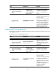
Task Command Remarks
Clear LACP statistics for a specific
or all link aggregation member
ports.
reset lacp statistics [ interface interface-list ]
Available in user
view.
Clear statistics for a specific or all
aggregate interfaces.
reset counters interface [ { bridge-aggregation |
route-aggregation } [ interface-number ] ]
Available in user
view.
Ethernet link aggregation configuration examples
In an aggregation group, only ports that have the same port attributes and class-two configurations (see
"Configuration classes") as the refe
rence port (see "Reference port") can operate as Selected ports.
Make sure all member ports have the same port attributes and class-two configurations as the reference
port. The other settings only need to be configured on the aggregate interface, not on the member ports.
Layer 2 static aggregation configuration example
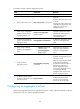
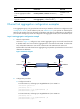
1. Network requirements
As shown in Figure 73, configure a Layer 2 static aggregation grou
p on Firewall A and Firewall
B. Enable VLAN 10 at one end of the aggregate link to communicate with VLAN 10 at the other
end, and enable VLAN 20 at one end to communicate with VLAN 20 at the other end.
Enable traffic to be load-shared across aggregation group member ports based on the source and
destination IP addresses.
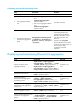
Figure 73 Network diagram
2. Configuration procedure
a. Configure Firewall A:
# Create VLAN 10, and assign port GigabitEthernet 0/3 to VLAN 10.
<FirewallA> system-view
[FirewallA] vlan 10
[FirewallA-vlan10] port gigabitethernet 0/3
[FirewallA-vlan10] quit
# Create VLAN 20, and assign port GigabitEthernet 0/4 to VLAN 20.
[FirewallA] vlan 20
[FirewallA-vlan20] port gigabitethernet 0/4
[FirewallA-vlan20] quit
GE0/1
GE0/2
Link aggregation 1
GE0/1
GE0/2
BAGG1 BAGG1
Firewall A Firewall B
VLAN 10
VLAN 20
GE0/3
GE0/4
VLAN 10
VLAN 20
GE0/3
GE0/4