
HP VPN Firewall Appliances High Availability Configuration Guide

164
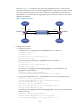
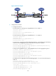
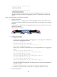
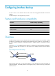
As shown in Figure 74, configure a Layer 2 dynamic aggregation group on Firewall A and
Firewall B. Enable VLAN 10 at one end of the aggregate link to communicate with VLAN 10 at the
other end, and enable VLAN 20 at one end to communicate with VLAN 20 at the other end.
Enable traffic to be load-shared across aggregation group member ports based on source and
destination IP addresses.
Figure 74 Network diagram
2. Configuration procedure
a. Configure Firewall A:
# Create VLAN 10, and assign the port GigabitEthernet 0/3 to VLAN 10.
<FirewallA> system-view
[FirewallA] vlan 10
[FirewallA-vlan10] port gigabitethernet 0/3
[FirewallA-vlan10] quit
# Create VLAN 20, and assign port GigabitEthernet 0/4 to VLAN 20.
[FirewallA] vlan 20
[FirewallA-vlan20] port gigabitethernet 0/4
[FirewallA-vlan20] quit
# Create Layer 2 aggregate interface Bridge-Aggregation 1, and configure the link
aggregation mode as dynamic.
[FirewallA] interface bridge-aggregation 1
[FirewallA-Bridge-Aggregation1] link-aggregation mode dynamic
# Assign ports GigabitEthernet 0/1 and GigabitEthernet 0/2 to link aggregation group 1.
[FirewallA] interface gigabitethernet 0/1
[FirewallA-GigabitEthernet0/1] port link-aggregation group 1
[FirewallA-GigabitEthernet0/1] quit
[FirewallA] interface gigabitethernet 0/2
[FirewallA-GigabitEthernet0/2] port link-aggregation group 1
[FirewallA-GigabitEthernet0/2] quit
# Configure Layer 2 aggregate interface Bridge-Aggregation 1 as a trunk port and assign it to
VLANs 10 and 20.
[FirewallA] interface bridge-aggregation 1
[FirewallA-Bridge-Aggregation1] port link-type trunk
[FirewallA-Bridge-Aggregation1] port trunk permit vlan 10 20
GE0/1
GE0/2
Link aggregation 1
GE0/1
GE0/2
BAGG1 BAGG1
Firewall A Firewall B
VLAN 10
VLAN 20
GE0/3
GE0/4
VLAN 10
VLAN 20
GE0/3
GE0/4