
HP VPN Firewall Appliances High Availability Configuration Guide

168
Bridge-Aggregation1 Load-Sharing Mode:
source-ip address
Bridge-Aggregation2 Load-Sharing Mode:
destination-ip address
The output shows that the load sharing criterion for link aggregation group 1 is the source IP
addresses of packets and that for link aggregation group 2 is the destination IP addresses of
packets.
Layer 3 static aggregation configuration example
1. Network requirements
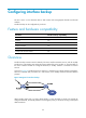
As shown in Figure 76, configure a Layer 3 static aggregation group on both Firewall A and
Firewall B and c
onfigure IP addresses and subnet masks for the corresponding Layer 3 aggregate
interfaces.
Enable traffic to be load-shared across aggregation group member ports based on source and
destination IP addresses.
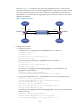
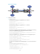
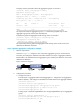
Figure 76 Network diagram
2. Configuration procedure
a. Configure Firewall A:
# Create Layer 3 aggregate interface Route-Aggregation 1, and configure an IP address and
subnet mask for the aggregate interface.
<FirewallA> system-view
[FirewallA] interface route-aggregation 1
[FirewallA-Route-Aggregation1] ip address 192.168.1.1 24
[FirewallA-Route-Aggregation1] quit
# Assign Layer 3 interfaces GigabitEthernet 0/1 through GigabitEthernet 0/3 to aggregation
group 1.
[FirewallA] interface gigabitethernet 0/1
[FirewallA-GigabitEthernet0/1] port link-aggregation group 1
[FirewallA-GigabitEthernet0/1] quit
[FirewallA] interface gigabitethernet 0/2
[FirewallA-GigabitEthernet0/2] port link-aggregation group 1
[FirewallA-GigabitEthernet0/2] quit
[FirewallA] interface gigabitethernet 0/3
[FirewallA-GigabitEthernet0/3] port link-aggregation group 1
[FirewallA-GigabitEthernet0/3] quit
# Configure the global link-aggregation load sharing criteria as the source and destination IP
addresses of packets.
[FirewallA] link-aggregation load-sharing mode source-ip destination-ip
b. Configure Firewall B in the same way Firewall A is configured. (Details not shown.)
3. Verify the configuration