
HP VPN Firewall Appliances High Availability Configuration Guide

170
[FirewallA] interface gigabitethernet 0/2
[FirewallA-GigabitEthernet0/2] port link-aggregation group 1
[FirewallA-GigabitEthernet0/2] quit
[FirewallA] interface gigabitethernet 0/3
[FirewallA-GigabitEthernet0/3] port link-aggregation group 1
[FirewallA-GigabitEthernet0/3] quit
# Configure Firewall A to use the source and destination IP addresses of packets as the global
link-aggregation load sharing criteria.
[FirewallA] link-aggregation load-sharing mode source-ip destination-ip
b. Configure Firewall B in the same way Firewall A is configured. (Details not shown.)
3. Verify the configuration:
# Display summary information about all aggregation groups on Firewall A.
[FirewallA] display link-aggregation summary
Aggregation Interface Type:
BAGG -- Bridge-Aggregation, RAGG -- Route-Aggregation
Aggregation Mode: S -- Static, D -- Dynamic
Loadsharing Type: Shar -- Loadsharing, NonS -- Non-Loadsharing
Actor System ID: 0x8000, 000f-e2ff-0001
AGG AGG Partner ID Select Unselect Share
Interface Mode Ports Ports Type
-------------------------------------------------------------------------------
RAGG1 D 0x8000, 000f-e2ff-0002 3 0 Shar
The output shows that link aggregation group 1 is a load-shared Layer 3 dynamic aggregation
group and it contains three Selected ports.
# Display the global link-aggregation load sharing criteria on Firewall A.
[FirewallA] display link-aggregation load-sharing mode
Link-Aggregation Load-Sharing Mode:
destination-ip address, source-ip address
The output shows that the global link-aggregation load sharing criteria are the source and
destination IP addresses of packets.
Layer 3 aggregation load sharing configuration example
1. Network requirements
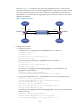
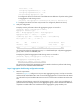
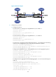
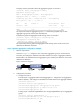
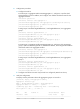
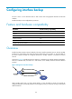
As shown in Figure 78, configure two Layer 3 static aggregation groups (1 and 2) on both Firewall
A and Firewall B, and configur
e IP addresses and subnet masks for the corresponding Layer 3
aggregate interfaces.
Configure link aggregation group 1 to perform load sharing based on source IP address and link
aggregation group 2 to perform load sharing based on destination IP address.
Figure 78 Network diagram