
HP VPN Firewall Appliances High Availability Configuration Guide
180
Configuration procedure
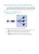
1. Configure IP addresses:
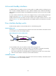
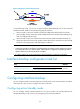
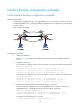
Follow Figure 83 to configure the IP address and subnet mask for each interfa
ce. (Details not
shown.)
2. Configure a static route:
# On Firewall A, configure a static route to the segment 192.168.2.0/24 where Host B resides.
<FirewallA> system-view
[FirewallA] ip route-static 192.168.2.0 24 gigabitethernet 0/1 1.1.1.2
[FirewallA] ip route-static 192.168.2.0 24 gigabitethernet 0/2 2.2.2.2
[FirewallA] ip route-static 192.168.2.0 24 gigabitethernet 0/3 3.3.3.2
# On Firewall B, configure a static route to the segment 192.168.1.0/24 where Host A resides.
<FirewallB> system-view
[FirewallB] ip route-static 192.168.1.0 24 gigabitethernet 0/1 1.1.1.1
[FirewallB] ip route-static 192.168.1.0 24 gigabitethernet 0/2 2.2.2.1
[FirewallB] ip route-static 192.168.1.0 24 gigabitethernet 0/3 3.3.3.1
3. Configure the standby interfaces and load balancing on Firewall A:
# Specify interfaces GigabitEthernet 0/2 and GigabitEthernet 0/3 on Firewall A to back up
GigabitEthernet 0/1, and assign them the priorities 30 and 20, respectively.
[FirewallA] interface gigabitethernet 0/1
[FirewallA-GigabitEthernet0/1] standby interface gigabitethernet 0/2 30
[FirewallA-GigabitEthernet0/1] standby interface gigabitethernet 0/3 20
# Configure the available bandwidth used for setting the thresholds to 10000 kbps.
[FirewallA-GigabitEthernet0/1] standby bandwidth 10000
# Configure the enable-threshold of load balancing to 80 and the disable-threshold to 20.
[FirewallA-GigabitEthernet0/1] standby threshold 80 20
4. Verify the configuration on Firewall A:
# Display the traffic statistics for the active interface taking part in load balancing.
[FirewallA-GigabitEthernet0/1] display standby flow
Interfacename : GigabitEthernet0/1
Flow-interval(s) : 30
LastInOctets : 139
LastOutOctets : 22033
InFlow(Octets) : 0
OutFlow(Octets) : 0
BandWidth(b/s) : 10000
UsedBandWidth(b/s) : 0
# Display the state of the active and standby interfaces.
[FirewallA-GigabitEthernet0/1] display standby state
Interface Interfacestate Standbystate Standbyflag Pri Loadstate
GigabitEthernet0/1 UP MUP MUD TO-HYPNOTIZE
GigabitEthernet0/2 STANDBY STANDBY BU 30
GigabitEthernet0/3 STANDBY STANDBY BU 20
Backup-flag meaning:
M---MAIN B---BACKUP V---MOVED U---USED
D---LOAD P---PULLED