
HP VPN Firewall Appliances High Availability Configuration Guide

186
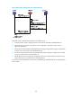
1. The host sends a request, using VSIP as the destination address.
2. Upon receiving the request, the general device forwards it to LB device. The VSIP cannot be
contained in an ARP request and response, so the general device only forwards the request to the
LB device.
3. Upon receiving the request, the LB device uses an algorithm to calculate to which server it
distributes the request.
4. The LB device distributes the request. The LB device encapsulates VSIP as the destination IP address,
and the server's MAC address (obtained through ARP) as the destination MAC address. In this
way, the request can be forwarded correctly to the server.
5. The server receives and processes the request, and then sends a response. The destination IP
address of the response is the host IP.
6. After receiving the response, the general device forwards the response to the host. The response
is addressed to the host rather than the LB device, so DR-mode server load balancing is called.
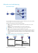
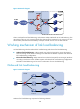
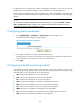
Working mechanism of firewall load balancing
Firewall load balancing supports IPv4 and IPv6.
Figure 88 Network diagram
Firewall load balancing comprises the following elements:
• Cluster—A cluster consists of LB devices and firewalls to provide network traffic load balancing.
• LB device—A device that distributes traffic from the request sender to multiple firewalls. LB devices
include level 1 LB devices and level 2 LB devices. In Figure 88, if traffic is from Host A to Host B, LB
devic
e A is level 1, and LB device B is level 2. If traffic is from Host B to Host A, LB Device B is level
1, and LB Device A is level 2.
• Firewall—A firewall filters packets.