
HP VPN Firewall Appliances High Availability Configuration Guide

188
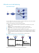
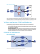
Figure 90 Network diagram
Cluster A adopts firewall load balancing, and Cluster B adopts NAT-mode server load balancing. This
networking mode not only prevents firewalls from becoming the bottleneck in the network, but also
enhances the performance and availability of multiple network services such as HTTP and FTP.
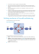
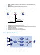
Working mechanism of link load balancing
Link load balancing includes outbound link load balancing and inbound link load balancing:
• Outbound link load balancing—Helps internal users select the best path to access the external
resources through an LB device according to the destination IP address of packets and outbound
link load balancing configurations.
• Inbound link load balancing—Helps external users select the best path for accessing an LB device
according to the domain name of DNS requests and inbound link load balancing configurations.
Inbound link load balancing can be used in combination of server load balancing.
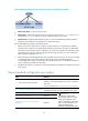
Outbound link load balancing
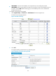
Figure 91 Network diagram
Outbound link load balancing comprises the following elements:
ISP1
ISP2
ISP3
IP network
Router A
Router B
Router C
LB device
VSIP
Source Destination
Cluster