
HP VPN Firewall Appliances High Availability Configuration Guide

232
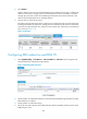
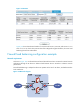
Figure 135 Statistics
Figure 135 shows that the total number of connections of Server A, Server B, and Server C is in a
ratio of 15:12:10, which is the same as that of the configured weights. Therefore, the server load
balancing function has taken effect.
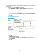
Firewall load balancing configuration example
Network requirements
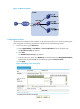
As shown in Figure 136, two firewalls Firewall A and Firewall B each are connected to internal network
and Internet through an LB device to balance load between the two networks to enhance network
performance.
Firewall load balancing is adopted. LB device A operates as the level 1 LB device, and LB device B the
level 2 LB device.
Figure 136 Network diagram