
HP VPN Firewall Appliances High Availability Configuration Guide

236
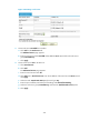
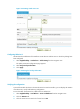
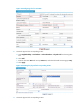
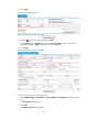
You can see the statistics on the page.
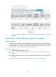
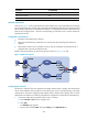
Figure 141 Statistics on LB device A
Figure 141 shows that the traffic from the internal network to Internet is balanced by Firewall A and
Firewall B.
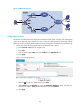
Outbound link load balancing configuration example
Network requirements
A user has rent two physical links ISP1 and ISP2 from a carrier. The router hops, bandwidth and cost of
the two links are the same, but the network delay of ISP2 is smaller than that of ISP1. It is hoped that
packets destined to the IP address in the 10.66.3.0/24 segment are transmitted on ISP1, and packets
destined to other addresses use the optimal link between the two links.
Configuration considerations
• Outbound link load balancing is required.
• Packets are transmitted to the destination over the best link: Best performing link detection is
adopted.
• Packets with the destination in the 10.66.3.0/24 segment are transmitted on physical link ISP1: ACL
is adopted.
Based on the above analysis, the networking scheme as shown in Figure 142 is adopted.