
HP VPN Firewall Appliances High Availability Configuration Guide

239
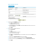
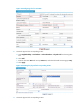
a. Click Add on the Physical Link tab.
b. Enter the link name ISP2 and next hop 100.0.0.1, and select the health monitoring type icmp.
c. Click Apply.
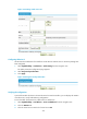
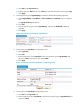
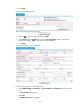
4. Create logical link group LogicalLinkGrp and adopt the bandwidth scheduling algorithm:
a. Select High Reliability > Load Balance > Link Load Balance > Outbound from the navigation
tree.
The Logical Link Group tab appears.
b. Click Add.
c. Enter the logical link group name LogicalLinkGrp, and select the Bandwidth scheduling
algorithm.
d. Click Apply.
Figure 146 Creating logical link group LogicalLinkGrp
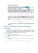
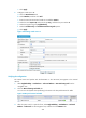
5. Create logical link LogicalLink1 corresponding to ISP1:
a. Click Logical Link.
b. Click Add.
c. Enter the logical link name LogicalLink1, select the logical link group LogicalLinkGrp and
physical link ISP1, and enter the ACL number 3000.
d. Click Apply.
Figure 147 Creating logical link LogicalLink1 corresponding to ISP1
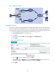
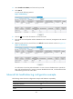
6. Create logical link LogicalLink2 corresponding to ISP2:
a. Click Add on the Logical Link tab.
b. Enter the logical link name LogicalLink2, and select the logical link group LogicalLinkGrp and
physical link ISP2.