
HP VPN Firewall Appliances High Availability Configuration Guide

242
Hardware Com
p
atibilit
y
F5000-S/F5000-C No
VPN firewall modules No
20-Gbps VPN firewall modules No
Network requirements
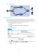
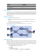
As shown in Figure 152, Server (with the domain name whatever.com.cn) provides Web services through
two rent physical links ISP 1 and ISP 2. The router hops, bandwidth, and cost of the two links are the same,
but the network delay of ISP 2 is smaller than that of ISP 1. It is hoped that users that correspond to local
DNS server B use physical link 1 and users corresponding to local DNS server A use the optimal link
between the two links.
Configuration considerations
• Inbound link load balancing is required.
• Packets are transmitted to the destination over the best link. Best performing link detection is
adopted.
• DNS requests with the source IP address 10.66.3.1/24 are transmitted over physical link ISP 1:
Configure DNS A records, and reference ACL.
Based on the above analysis, the networking scheme as shown in Figure 152 is used.
Figure 152 Network diagram
Configuring the LB device
Assume ISP 1 and ISP 2 have been deployed successfully and their status is healthy, and other features
such as the IP addresses of the interfaces on the LB device, the zone to which they belong, and routing
of the LB device have been configured; DNS requests with the domain name whatever.com.cn can be
distributed to the LB device. The following describes the configuration of inbound link load balancing.
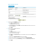
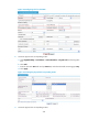
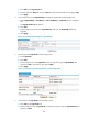
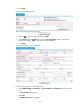
1. Create ACL 3000, allowing packets with the source 10.66.3.1:
a. Select Firewall > ACL from the navigation tree.
b. Click Add.
The Add ACL page appears.
c. Enter the ACL number 3000, and select Config from the Match Order list.