
HP VPN Firewall Appliances High Availability Configuration Guide

25
IPv4 VRRP configuration examples
Single VRRP group configuration example (in the Web
interface)
Network requirements
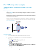
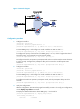
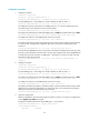
As shown in Figure 12, Host A wants to access Host B on the Internet, using 202.38.160.111/24 as its
default gateway. Firewall A and Firewall B belong to VRRP group 1 with the virtual IP address
2 0 2 . 3 8 .16 0 .111/24.
If Firewall A operates correctly, the packets that Host A sends to Host B are forwarded by Firewall A. If
GigabitEthernet 0/2 connecting Firewall A to the Internet becomes unavailable, packets sent from Host
A to Host B are forwarded by Firewall B.
To prevent spoof attacks to the VRRP group from unauthorized users, configure the authentication mode
as plain text to authenticate the VRRP packets in VRRP group 1. Specify the authentication key as hello.
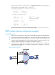
Figure 12 Network diagram
Configuring Firewall A
1. Configure the IP address of each interface and the zones. (Details not shown.)
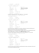
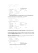
2. Create VRRP group 1 on GigabitEthernet 0/1 and configure the virtual IP address as
202.38.160.111:
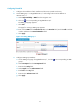
a. Select High Availability > VRRP from the navigation tree.
b. Click the icon corresponding to GigabitEthernet 0/1.
The VRRP group page appears.
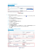
c. Click Add.
The page for creating a VRRP group appears.
d. Enter 1 in the VRID field and 202.38.160.111 in the Virtual IP field, and then click Add to add
the virtual IP address to the Virtual IP Members field.
e. Click Apply.