
HP VPN Firewall Appliances High Availability Configuration Guide

38
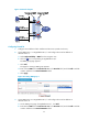
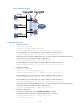
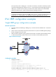
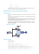
Figure 23 Network diagram
Configuration procedure
1. Configure Firewall A:
<FirewallA> system-view
[FirewallA] interface gigabitethernet0/1
[FirewallA-GigabitEthernet0/1] ip address 202.38.160.1 255.255.255.0
# Create VRRP group 1 and configure its virtual IP address as 202.38.160.111.
[FirewallA-GigabitEthernet0/1] vrrp vrid 1 virtual-ip 202.38.160.111
# Set the priority of Firewall A in VRRP group 1 to 110, which is higher than that of Firewall B (100),
so that Firewall A can become the master in VRRP group 1.
[FirewallA-GigabitEthernet0/1] vrrp vrid 1 priority 110
# Create VRRP group 2 and configure its virtual IP address as 202.38.160.112.
[FirewallA-GigabitEthernet0/1] vrrp vrid 2 virtual-ip 202.38.160.112
2. Configure Firewall B:
<FirewallB> system-view
[FirewallB] interface gigabitethernet0/1
[FirewallB-GigabitEthernet0/1] ip address 202.38.160.2 255.255.255.0
# Create VRRP group 1 and configure its virtual IP address as 202.38.160.111.
[FirewallB-GigabitEthernet0/1] vrrp vrid 1 virtual-ip 202.38.160.111
# Create VRRP group 2 and configure its virtual IP address as 202.38.160.112.
[FirewallB-GigabitEthernet0/1] vrrp vrid 2 virtual-ip 202.38.160.112
# Set the priority of Firewall B in VRRP group 2 to 110, which is higher than that of Firewall A (100),
so that Firewall B can become the master in VRRP group 2.
[FirewallB-GigabitEthernet0/1] vrrp vrid 2 priority 110
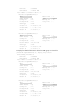
3. Verify the configuration:
To verify your configuration, use the display vrrp verbose command.
# Display the detailed information about the VRRP group on Firewall A.
[FirewallA-GigabitEthernet0/1] display vrrp verbose
IPv4 Standby Information: